Mercury SmartCraft Systems Monitor Operation Manual
Hide thumbs
Also See for SmartCraft Systems Monitor:
- Operation manual (96 pages) ,
- Installation manual (10 pages) ,
- Wiring connections (5 pages)

Related Manuals for Mercury SmartCraft Systems Monitor


Summary of Contents for Mercury SmartCraft Systems Monitor
- Page 1 Systems Monitor Operation Manual THIS MANUAL DESCRIBES THE SMARTCRAFT GAUGE SYSTEMS AVAILABLE FOR YOUR BOAT 2004, Mercury Marine 90-895202 204...
-
Page 3: Table Of Contents
TABLE OF CONTENTS Legend ..........Basic Operation . -
Page 5: Legend
LEGEND = Engine = Fuel = Water Temperature = Water Pressure = Oil = Alarm... -
Page 6: Basic Operation
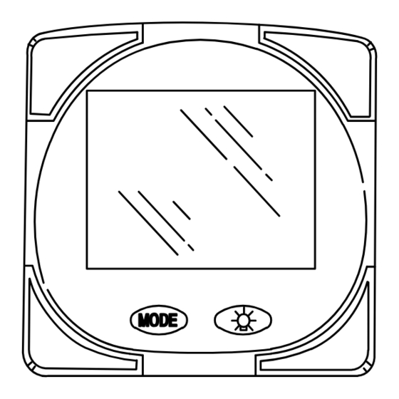
BASIC OPERATION The Monitor is an LCD multi-function display gauge. A variety of displays can be activated using the button. Pressing the button scrolls the following displays: fuel used, tachometer (RPM), fuel flow, power trim position, engine temp, water pressure, battery voltage, range (if calibrated), and water depth (if equipped with transducer). - Page 7 BASIC OPERATION Initial Power Up (Or After Master Reset) INITIAL AUTO-DETECTION ERROR MESSAGES: Flashing “Stbd” – More than one of the engine computers (ECMs) are configured as a starboard engine. The engines must be programmed for proper engine location using a DDT or Quicksilver Diagnostic Tool.
-
Page 8: Master Reset
MASTER RESET You can return the gauge back to factory presets through the Master Reset command. IMPORTANT: Performing a master reset will reset the unit back to all factory defaults, thus eliminating any installation calibrations performed during set up of product. 1. -
Page 9: Standard Display Screens
STANDARD DISPLAY SCREENS NOTE:This manual shows all the Monitor display screens that are available. Depending on your type of engine, not all these screens will apply. Start Up At start up, a momentary (1 second) screen displays the current monitor software version, followed by a 4 second Software Version... - Page 10 STANDARD DISPLAY SCREENS Trim Position TRIM Displays trim position of the pro- pulsion unit up to the maximum trim position, and then displays the trailer position. 0 = down, 10 = full trim 25 = full trailer. NOTE: This screen can be set to pop up whenever the trim switch is used.
- Page 11 STANDARD DISPLAY SCREENS Oil Pressure Displays engine oil pressure in Psi or Bar. Battery Voltage Displays voltage level (condition) of battery. Volt Range Range Displays estimated range based on current fuel consump- tion and fuel remaining in the Miles tank that is connected to the system.
- Page 12 STANDARD DISPLAY SCREENS Water Depth Depth Displays the depth of water un- der the transducer if connected. You must have a depth NOTE: transducer (purchased separate- ly) connected to the system in or- der for this screen to operate. Vessel Speed Displays the vessel speed.
-
Page 13: Shallow Water Alarm
Shallow Water Alarm You can set an alarm to trigger whenever the boat moves into water shallower than the alarm level. Setting Shallow Water Alarm. 1. The water depth screen must be displayed. Be sure Depth is turned on in CAL 2. Refer to CAL 2 Calibration Section. 2. -
Page 14: Warning System
WARNING SYSTEM When a problem is detected with the engine, the warning display screens will alert the operator to the potential problem. Refer to the Engine Operation, Maintenance and Warranty Manual for explanation of the problem and the correct action to take. If problem can cause immediate engine damage, the Engine Guardian System will respond to the problem by limiting engine power. - Page 15 WARNING SYSTEM Warning Display Screens IMPORTANT: Refer to the Engine Operation, Maintenance and Warranty Manual for further explanation of the problem and the correct action to take. Water in Fuel The Bell and Fuel Icon are dis- played. Water in the water-sep- arating fuel filter reached the full level.
-
Page 16: Cal 1 Calibration
CAL 1 CALIBRATION Cal1 Display Calibrations: •(On or Off) Trim Pop up Screen •Trim Calibration •English or Metric Units Selection •Range/Distance Units Selection •(On or Off) Depth, Trim, Engine Temperature, Oil Pressure, Oil Temperature, Water Pressure, Volts, Engine Hours,Speed, Sea- water Temperature and Data Simulator pages. - Page 17 CAL 1 CALIBRATION Trim Sensor Trim 0.0 Setting (Full Trim in Position) 1. The word “Trim” and down arrow should be blinking. 2. Trim unit to the full Down/In position. 3. Press the button to save. 4. Press the button to advance to 10.0 setting. Trim Sensor Trim 10.0 Setting...
- Page 18 CAL 1 CALIBRATION English or Metric SAE English System Metric System Select whether you want the readings in the SAE English system or the Metric system. 1. Press the button to toggle between units. 2. Press the button to move to the next function. Range Readings Range Select whether you want the...
- Page 19 CAL 1 CALIBRATION Coolant Temperature Display (on or off) Select whether you want the coolant temperature screen to be displayed. 1. Press the button to select on or off. 2. Press the button to move to the next function. Oil Pressure Display (on or off) Select whether you want the oil pressure screen to be dis-...
- Page 20 CAL 1 CALIBRATION Water Pressure Display (on or off) Select whether you want the water pressure screen to be dis- played. 1. Press the button to select on or off. 2. Press the button to move to the next function. Battery Voltage Display (on or off) Volt...
- Page 21 1. Press the button to select on or off. 2. Press the button to move to the next function. Seawater Temperature Display (on or off) Select whether you want sea- water temperature screen to be displayed. 1. Press the button to select on or off. 2.
-
Page 22: Cal 2 Calibration
Sensor Input Select the pressure input of the Pitot water pressure sensor on the engine. NOTE:The standard speed in- put on production Mercury Out- boards is 100 PSI. Certain High Performance applications may require a 200 PSI input. 1. Press the button to select. - Page 23 Frequency can be changed to match requirements of different Miles sensors. 4.9 is the frequency of the paddle wheel speed sensor provided by Mercury Marine. Press the button to save and move to the next function. Seawater Temperature Display (on or off) Indicates if a seawater tempera- ture sensor is installed.
-
Page 24: Fuel Tank Calibration
CAL 2 CALIBRATION Fuel Tank Calibration THERE ARE THREE METHODS TO SET UP THE FUEL TANK LEVEL MONITORING FEATURE: First: Do nothing. Linear readout based on raw sensor values. This mode does not factor in irregular tank shapes. Second: By following the tank calibration default procedure, which is done without actually adding fuel to the tank. - Page 25 CAL 2 CALIBRATION CAL 2 Calibration Tank 1 (fuel) Capacity Setting “t1” = tank 1 1. Press the button until “t1” is displayed. “t1” = tank 1. 2. Press once more. The word “no” and the fuel icon will be displayed.
- Page 26 CAL 2 CALIBRATION Tank 1 Calibration Once the capacities have been entered, you need to select whether you want to calibrate fuel tank 1 ” ’t1”. NOTE: The gauge will not let you calibrate the fuel tank until the ca- pacity had been entered).
- Page 27 CAL 2 CALIBRATION Tank 1 Calibration 50% Setting Adding the amount of fuel shown will raise fuel tank level to 50 per- 50 Percent Fuel to Add cent. NOTE:The quantity of “Fuel to Add” is determined by the fuel tank capacity number entered. 5.
- Page 28 CAL 2 CALIBRATION Tank 2 Calibration Select whether you want to cali- brate tank 2. NOTE: Tank 2 does not have to be a fuel tank. It could represent an oil tank for example. NOTE: The gauge will not let you calibrate the tank until the capac- ity had been entered).
- Page 29 CAL 2 CALIBRATION Tank 2 Calibration 25% Setting Adding the amount of fuel shown will raise fuel tank level to 25 per- 25 Percent Fuel to Add cent. NOTE :The quantity of fuel to add is determined by the fuel tank ca- pacity number entered.
- Page 30 CAL 2 CALIBRATION Tank 2 Calibration 75% Setting Adding the amount of fuel shown will raise fuel tank level to 75 per- Fuel to Add 75 Percent cent. NOTE:The quantity of fuel to add is determined by the fuel tank ca- pacity number entered.
Need help?
Do you have a question about the SmartCraft Systems Monitor and is the answer not in the manual?
Questions and answers