Table of Contents
Advertisement
Quick Links
Advertisement
Chapters
Table of Contents

Related Manuals for Mercury VesselView 403


Summary of Contents for Mercury VesselView 403
- Page 1 VesselView O PERA TION M A N U A L...
- Page 4 Device Maintenance..............5 Test Report................2 Display Screen Cleaning............5 VesselView Overview..............2 Media Port Cleaning............. 5 VesselView 403 Front Panel............3 Electrical connections............5 VesselView 403 Rear Panel............4 Section 2 - Initial Screens and Setup Wizard Splash Screen................8 Speed Setup..............
- Page 5 Section 4 - Software Update Procedure Checking the Current Software Version......... 58 Updating through a Wi‑Fi Connection........58 Downloading the Current Software......... 58 Updating through the USB Port..........64 Page ii 90-8M0124182 DECEMBER 2017...
-
Page 6: Table Of Contents
Standard ................. 2 Device Maintenance............... 5 Test Report ..............2 Display Screen Cleaning ..........5 VesselView Overview............. 2 Media Port Cleaning ............5 VesselView 403 Front Panel..........3 Electrical connections ............. 5 VesselView 403 Rear Panel........... 4 90-8M0124182 DECEMBER 2017 Page 1... -
Page 7: Declaration Of Conformity
Section 1 - Getting Started Declaration of Conformity Mercury Marine declares that the following product to which this declaration relates is in conformity with the requirements of EU directive 2014/30/EU (Electromagnetic Compatibility), and Section 182 of the Australian Radiocommunications (Electromagnetic Compatibility) standard 2008, and satisfies all the technical regulations applicable. -
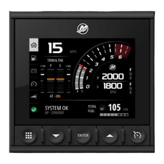
Page 8: Vesselview 403 Front Panel
2.2 W (maximum) Power supply NMEA 2000® NMEA 2000 load equivalency number 4 network loads VesselView 403 Front Panel VesselView 403 utilizes five hard buttons with no touchscreen functionality. Front controls Menu button Down arrow button Enter button Up arrow button... -
Page 9: Vesselview 403 Rear Panel
VesselView 403 Rear Panel The wiring connection points on the rear panel of the VesselView allow for the connection of the Mercury SmartCraft network communication cable, and for the unit to communicate over a NMEA 2000 network. There is also an USB port for utilizing a wi‑fi dongle, as well as for connecting a portable storage device for updating software, uploading vessel personalities, or... -
Page 10: Device Maintenance
Section 1 - Getting Started Device Maintenance IMPORTANT: It is recommended that the supplied white plastic sun cover be installed for protection when the unit is not in service. Display Screen Cleaning Routine cleaning of the display screen is recommended to prevent a buildup of salt and other environmental debris. Crystalized salt can scratch the display coating when using a dry or damp cloth. - Page 11 Section 1 - Getting Started Notes: Page 6 90-8M0124182 DECEMBER 2017...
-
Page 12: Section 2 - Initial Screens And Setup Wizard
Section 2 - Initial Screens and Setup Wizard Section 2 - Initial Screens and Setup Wizard Table of Contents Splash Screen................ 8 Speed Setup..............11 Setup Wizard................8 Units Setup..............14 Overview................8 Tank Setup..............14 Import Configuration............9 Active Trim Setup............18 Engine Setup.............. -
Page 13: Splash Screen
Section 2 - Initial Screens and Setup Wizard Splash Screen Upon startup, VesselView will display an initial splash screen. An image of an engine in the lower corner indicates that the engine power on the vessel is emission controlled. 64808 Splash screen Setup Wizard Overview... -
Page 14: Import Configuration
In the engine setup section of the setup wizard, the operator can select the engine model, the number of engines on the vessel, and the number of engines, up to two, which will be displayed on a particular VesselView. NOTE: VesselView 403 will only display data for two engines. Vessels with three or more engines will require additional VesselView 403 units. - Page 15 VesselView. A maximum of two engines can be displayed on a single VesselView 403. When finished with the Engine Setup portion of the Wizard, press the Menu button to return to the Engine Setup screen. Press the Down arrow button to continue to the next step of the Wizard.
-
Page 16: Device Setup
Section 2 - Initial Screens and Setup Wizard Device Setup In the Device Setup screen, use the up and down arrow buttons and the Enter button to confirm selection. If using multiple VesselView devices, be sure to assign unique numbers to each unit to avoid data transmission problems. Helm numbers should match the location of the individual VesselView unit. - Page 17 Section 2 - Initial Screens and Setup Wizard Highlight and select the GPS Source. 64825 Speed source selection For GPS speed data, select the CAN Bus that transmits the GPS data over the SmartCraft network. 65293 Highlight and select the Speed Source option. 65292 Page 12 90-8M0124182...
- Page 18 Section 2 - Initial Screens and Setup Wizard For a speed Strategy, highlight and select the Pitot source option and choose the engine PCM that will report the data from the pitot sensor. 65294 64827 Engine position selection Select the Paddle source option and choose the engine PCM that will report data from the paddlewheel sender. 65295 90-8M0124182 DECEMBER 2017...
-
Page 19: Units Setup
Section 2 - Initial Screens and Setup Wizard 64827 Engine position selection The PCM positions for vessels with multiple engines is shown in the following illustration. 60056 PCM0 = starboard outer PCM1 = port outer PCM2 = starboard inner or center PCM3 = port inner When selections are completed in the Speed Setup portion of the Wizard, press the Down arrow button to continue to the next step of the Wizard. - Page 20 Section 2 - Initial Screens and Setup Wizard With Tanks highlighted, press the Enter button to continue. 65337 With the Configure new tank highlighted, press the Enter button. 65338 The tank configuration screen contains all of the information that VesselView will require to display accurate tank data. Tank configuration screen Detected tank sensor Type of tank...
- Page 21 Section 2 - Initial Screens and Setup Wizard To select the tank type, use the Up arrow and Down arrow buttons to highlight the desired tank type. With the tank type selected, press the Enter button. 65340 Enter the name of the tank. Up to nine characters can be entered into the name field. Refer to Section 3 ‑ Entering Text and Numbers.
- Page 22 Section 2 - Initial Screens and Setup Wizard VesselView gives the operator the ability to invert the volume value of the tanks being monitored. This option is available to accommodate some tank senders that transmit data opposite of traditional standard senders. Standard tank level senders read a 33–240 ohm resistance.
-
Page 23: Active Trim Setup
Wizard menu and press the Down arrow button to continue with the wizard. Active Trim Setup Vessels with Mercury Marine's Active Trim installed can manage trim profiles using the VesselView display. Functionality of the Active Trim keypad will not be affected. -
Page 24: Finishing Setup Wizard
Section 2 - Initial Screens and Setup Wizard Follow the on‑screen instructions to complete the trim up adapt. Press the Enter button to continue. 65719 VesselView will display the Major Profile screen when trim down and trim up adapt is complete. There is no need to calibrate each of the five major trim profiles. -
Page 25: Source Selection Notice
Section 2 - Initial Screens and Setup Wizard Source Selection Notice Upon completion of the setup Wizard, a Source selection notice is displayed. Selecting Start, by pressing the Enter button, will begin the process of searching the vessel's network for identifiable sensors and senders of data transmitting devices. 65793 Data source selection in progress. - Page 26 Section 2 - Initial Screens and Setup Wizard To create a screen capture press the Menu and Speed Control buttons at the same time. A screen capture file name will briefly appear at the bottom of the screen. 64792 Menu and Speed Control buttons All screen captures are located within the File Browser folder, which is in the main menu.
- Page 27 Section 2 - Initial Screens and Setup Wizard NOTE: In order to see the Copy to USB option, a properly formatted USB drive must be plugged into the back of the VesselView unit. The USB connection is located under the large cap on the rear of the unit. 64848 64849 Screenshots copied to USB drive...
-
Page 28: Section 3 - Main Menu Selections
Section 3 - Main Menu Selections Section 3 - Main Menu Selections Table of Contents Overview................24 Network ..............47 Enlarging Data Screens............24 Simulate ..............48 Entering Text and Numbers..........25 Time ..............49 Home..................25 Check for Updates ..........49 Active Trim ................ -
Page 29: Overview
Section 3 - Main Menu Selections Overview Pressing the Menu button will bring up the main Menu screen. Use the Up arrow and Down arrow buttons to navigate and highlight the desired menu item. Anytime a selection is made from the main Menu screen, pressing the Menu button will take the operator out of the selection and back to the main Menu screen. -
Page 30: Entering Text And Numbers
Section 3 - Main Menu Selections Pressing the Up arrow button until the Home icon is highlighted will return the VesselView to the active display screen. 64857 System Panel Additional enlarged data screens can be accessed by pressing the Menu button and using the Up arrow or Down arrow to select any of the menu items. -
Page 31: Active Trim
Settings>Preferences>Interface>System. A maximum of five data selections can be made. Active Trim 65736 Additional hardware for your vessel may be required for the Active Trim features to function. See your authorized Mercury Marine dealer for information on required hardware. Introduction to Active Trim Active Trim is Mercury Marine’s patented GPS‑based automatic trim system. -
Page 32: Gps
Section 3 - Main Menu Selections 2. Acceleration (hole shot) Tucks the engine or drive under to minimize bow rise and improve time‑to‑plane. 61897 3. Planing speeds Progressively trims the engine or drive based on GPS speed to maintain the most efficient running attitude. -
Page 33: Setup And Configuration
Section 3 - Main Menu Selections Configure the Active Trim system with the major trim profile that is most appropriate for an individual boat and power package combination under normal operating conditions. Each major profile curve shown in the preceding example represents the default, middle setting (adjustable trim profile 3) of a broader range of adjustable trim profiles. - Page 34 Section 3 - Main Menu Selections 64875 64876 64878 64879 90-8M0124182 DECEMBER 2017 Page 29...
-
Page 35: Fuel
Section 3 - Main Menu Selections Fuel The VesselView Fuel screen displays the total fuel based on the current tank data entered in the tank configuration through the tanks menu or the setup wizard. The lower portion of the screen will show the fuel flow, or fuel consumption in volume per hour. The volume will be dependent on the units of measure that was selected during the setup wizard process. -
Page 36: Trim/Tabs
Section 3 - Main Menu Selections Trim/Tabs The following data is displayed on the Trim/Tabs data screen: • Trim graph • Tab graph • Numeric trim values • Active Trim status • Fuel flow rate Trim graph Numeric trim value Active Trim status Fuel flow rate Tab graphs... - Page 37 Section 3 - Main Menu Selections In the main Menu, use the arrow buttons to highlight the Settings option and press the Enter button. 64959 Use the arrow buttons to highlight the Preferences option and press the Enter button. 64960 Use the arrow buttons to highlight the Interface option and press the Enter button.
-
Page 38: Smart Tow
Section 3 - Main Menu Selections Use the arrow buttons to highlight the System panel option and press the Enter button. 64962 In the System panel screen there are data display options. Use the arrow buttons to highlight a desired data selection. Press the Enter button to check or uncheck a selection. - Page 39 Section 3 - Main Menu Selections 65038 65039 Profiles 3 and 4 65040 Profile 5 The Smart Tow screen allows you to modify the set point for each profile. Changing the set point can be helpful when there are people onboard with varying levels of experience with water sports equipment. The operator can create more aggressive launches for experienced skiers, as well as mild launches for children or inflatables towing.
-
Page 40: Trip
Section 3 - Main Menu Selections To activate any Smart Tow launch profile, press the Enter button. 65036 To disable Smart Tow, press the Enter button. The display will exit the launch profile and return to where different profiles can be highlighted and launched. -
Page 41: Tanks
Faults History All Mercury warnings, faults, and alarms will be shown regardless of what screen is displayed at the time of the alarm. When an alarm is activated, the screen will display a window showing the alarm text and warning, along with a brief description of what action should be taken. - Page 42 To clear an active fault, the faulty part must be identified. Inspect, repair, or replace the faulty part. Start the engines and allow VesselView to go through the system start‑up scan. If the vessel passes the start‑up scan, the Mercury tab on the left‑hand side of the screen will display in green.
- Page 43 Section 3 - Main Menu Selections 64913 64914 No faults in Fault History When an active fault alert appears at the bottom of the screen, press the Enter button to view the fault information. 64915 64916 Page 38 90-8M0124182 DECEMBER 2017...
-
Page 44: Troll
Section 3 - Main Menu Selections Fault code Corrective action text Short text of fault Descriptive fault text Enter—to clear faults 65350 Troll Troll RPM ranges are power package dependent. The maximum troll RPM for all engines or outboards is 1000 RPM. 65005 The vessel must be in gear and the throttle must be at idle. - Page 45 Section 3 - Main Menu Selections Follow the on‑screen instructions at the bottom of the display. Pressing the Enter button will disable troll. Pressing the Speed Control button will allow for adjustments to the RPM set point. 65006 Onscreen instructions 65007 RPM adjustment button indicators Press the Speed Control button to exit out of the Adjust Speed/RPM window and return to the Troll screen.
-
Page 46: Performance
Section 3 - Main Menu Selections Performance The Performance screen will display the boat's peak speed, peak RPM, the current speed, and the current RPMs for up to two engines. 64882 Depth The Depth screen displays the water depth, along with the current trim position and water temperature. 64881 Genset The Genset data screen will display the following items:... -
Page 47: Maintenance
Section 3 - Main Menu Selections • Genset fuel—if defined in Tanks as a Genset tank 64964 Genset data screen Maintenance If a maintenance reminder is detected during a system scan, a pop‑up will appear on the screen in the color blue. Use common sense to protect your investment and check your engine oil on a regular basis, preferably before each use. -
Page 48: File Browser
Section 3 - Main Menu Selections The more blue shown in the bar represents a longer time before maintenance is required. The shorter the blue bar—depletion, indicates that scheduled maintenance will soon be required. The following images show a no maintenance required condition on the left and a maintenance required condition on the right. - Page 49 Section 3 - Main Menu Selections There are the options of reviewing the File Information, viewing the file, or deleting the file. 65010 Viewing the File Information will show the name of the file, the size of the file, and date and time which the file was created. File name File size Date and time of file creation...
-
Page 50: Settings
Section 3 - Main Menu Selections 65011 Local and removable storage locations Settings Within the Settings menu there are seven categories for setting or changing display data on the VesselView. Many of the settings are determined by selections made during the Setup Wizard, but these selections can be changed at any time by highlighting a category and selecting one of the associated options. -
Page 51: Helm
Section 3 - Main Menu Selections The Support... option at the bottom of the screen describes how to make a screen capture of the About screen. Capturing a screen is also covered in Section 2 ‑ Creating Screen Captures. 65022 Current software version and application revision Helm The Helm option allows the operator to assign a location identification number to the VesselView device and to the helm at... -
Page 52: Restore
Section 3 - Main Menu Selections Restore Restore will reset all of the customized settings on the VesselView. Checking the Local settings option will restore the settings on only the VesselView unit that is being used by the operator. Checking the Simnet global reset will reset all of the Simrad and Navico devices, as well as all of the VesselView units connected to the NMEA 2000 network. -
Page 53: Simulate
Section 3 - Main Menu Selections This will show a screen with devices and data sensors associated with the engine and vessel. Depending on the vessel's power package, some of the options will not apply. Press the Enter button to show a selection of sources for transmitting a device or sensor's data. -
Page 54: Time
Section 3 - Main Menu Selections Time Time is controlled by the vessel's GPS unit. When a GPS fix is established, the time display will be updated automatically. A local time offset can set the time from the time zone of departure, or the time zone of arrival if needed. In the time offset screen, use the buttons to navigate through the active data fields and apply the desired time offset. -
Page 55: Vessel
Section 3 - Main Menu Selections Vessel Vessel settings apply to sensors and senders on the boat that are separate from the engine package. Depending on how the vessel is rigged, some options may not be active. Items in the vessel settings include: Tabs, Tanks, Speed, Steering, Sea Temperature Source, and Joystick Installed. -
Page 56: Speed
Section 3 - Main Menu Selections Speed Speed data is covered during the setup wizard process, but changes to the way that VesselView obtains speed data can be made at any time. Selection of the CAN bus that transmits speed data can be changed. A speed strategy using pitot and paddlewheel sensors can be used on vessels that do not have a GPS receiver. -
Page 57: Sea Temperature Source
Section 3 - Main Menu Selections Steering Offset is used to align the outboard, sterndrive, or inboard to zero degrees. When the drive is positioned perpendicular to the hull, the steering angle displayed on‑screen may not match the steering sensor on the drive. To adjust for this variance, select the Offset window. -
Page 58: Number Of Engines
Limits helps set specific ranges for many engine data parameters such as: RPM, coolant temperature, oil temperature, battery voltage, and boost pressure. Changes made to limits will not affect the engine package or the operation of Mercury's Engine Guardian programming. The actual engine limits are determined by the factory programmed control module on the engine. -
Page 59: Backlight
Section 3 - Main Menu Selections Backlight The light level of the display can be changed in ten percent increments from 10 to 100 percent. This percentage will apply to all other SmartCraft displays and link gauges on the Vessel. To make the backlighting level of the VesselView unit be either dimmer or brighter than the other instruments, the Local gain can be changed to make viewing the VesselView screen more comfortable in varying lighting conditions. - Page 60 Section 3 - Main Menu Selections These types of faults will not turn the Mercury tab to red. Instead, the upper header bar will turn red and display the international warning symbol. In the Settings menu, select the Alarms option.
-
Page 61: Siren Enabled
Section 3 - Main Menu Selections • Save—stores any changes to the fault monitoring and data value Enable Data value Save 64923 Siren Enabled The Siren Enabled option will activate the horn in the VesselView to accompany the on‑screen pop‑up fault. Unchecking this box will disable the horn for fault pop‑ups. - Page 62 Section 4 - Software Update Procedure Section 4 - Software Update Procedure Table of Contents Checking the Current Software Version....... 58 Updating through a Wi‑Fi Connection........58 Downloading the Current Software........58 Updating through the USB Port..........64 90-8M0124182 DECEMBER 2017 Page 57...
-
Page 63: Checking The Current Software Version
Section 4 - Software Update Procedure Checking the Current Software Version The latest software for the VesselView is available on‑line for general download at Mercury's website; https:// www.mercurymarine.com. To understand what software version is in VesselView, power up VesselView. If VesselView is already powered up, navigate to the System Controls menu. - Page 64 Section 4 - Software Update Procedure To identify the Version and Application numbers of the current VesselView software, navigate to the Settings menu and highlight and select the System option. Highlight and select the About option to view the information. 65263 To update the VesselView software navigate to the Settings menu.
- Page 65 Section 4 - Software Update Procedure For the majority of operators, the Client option can be used to connect to a wireless internet source. 65253 Select the Connect to a wireless hotspot option. 65254 A screen showing all available wireless hotspots will be displayed. Use the Up arrow or Down arrow buttons to highlight and select the desired hotspot by pressing the Enter button.
- Page 66 Section 4 - Software Update Procedure If no wireless hotspots are detected, select the Rescan option to begin a fresh query of available hotspot options in the area. 65265 After a hotspot is selected, the operator will need to set the Authentication Mode to OPEN, and enter the Network Key or password if the hotspot connection is secured to complete the connection.
- Page 67 Section 4 - Software Update Procedure Highlight and select the Connect option by pressing the Enter button. 65260 The screen will display the connecting to data at the top. It may take up to a minute to establish the connection. 65261 When the wireless connection has been established the screen will display the connected information at the top.
- Page 68 Section 4 - Software Update Procedure IMPORTANT: Ensure that the wi‑fi dongle is inserted into the VesselView unit and a hotspot is accessible. 65264 If a newer version of the operating software is found, VesselView will prompt the operator to download the file or to ignore the update.
-
Page 69: Updating Through The Usb Port
Updating through the USB Port Download the current software release from the Mercury website. Copy the file to a USB drive with sufficient space. Turn the ignition key on and verify that the VesselView is on. Wait for a complete startup of the VesselView. - Page 70 Section 4 - Software Update Procedure NOTE: The following image is for illustrative purposes. The actual name of the update file will vary. 64937 VesselView will give the operator a prompt and an advisory screen. Do not power the unit off during the update process. Wait for the progress bar to show completion of the update.
Need help?
Do you have a question about the VesselView 403 and is the answer not in the manual?
Questions and answers
I,ve installed a vessel view 403 got power to it but none of the screens are reading.
The Mercury VesselView 403 may not display any readings despite having power due to a lack of connection to the Mercury SmartCraft network. The rear panel of the VesselView 403 includes wiring connection points for the Mercury SmartCraft network communication cable. If this cable is not properly connected or there is an issue with the network, the display will not receive data from the engine sensors. Checking the wiring connections and ensuring proper network communication can help resolve the issue.
This answer is automatically generated