Table of Contents
Advertisement
Quick Links
Redback® A 4565B Evacuation Controller
Operating Manual
A 4565B
Evacuation Controller
Optional Accessories
A 2078B Alert/Evac/Cancel Remote Wall Plate (Hard Wired)
A 2081 Alert/Evac/Chime/Cancel Remote Wall Plate (Hard Wired)
A 4578 Alert/Evac/Cancel Remote Wall Plate (U/UTP Cat5)
A 4581 Alert/Evac/Chime/Cancel Remote Wall Plate (U/UTP Cat5)
A 4581V Alert/Evac/Chime/Cancel Remote Wall Plate (U/UTP Cat5)
A 4597 Fire Test/Fire/Cancel Remote Wall Plate (U/UTP Cat5)
A 4658 Power Injector (U/UTP Cat5)
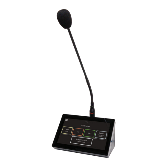
A 4660 Emergency Paging Microphone Console (U/UTP Cat5)
A 4660 Paging Console
A 2078B Remote Plate
A 2081 Remote Plate
A 4658 Power Injector
A 4581V Remote Plate
A 4578 Remote Plate
A 4581 Remote Plate
A 4597 Remote Plate
User manual revision number: 1.1 24/08/2023
Distributed by Altronic Distributors Pty. Ltd.
Distributed by Altronic Distributors Pty. Ltd.
Phone: 1300 780 999 Fax: 1300 790 999 Internet: www.altronics.com.au
Phone: 1300 780 999 Fax: 1300 790 999 Internet: www.altronics.com.au
IMPORTANT NOTE:
Please read these instructions carefully from front to back prior to installation.
They include important setup instructions.
Failure to follow these instructions may prevent the unit from working as designed.
www.redbackaudio.com.au
Redback® Proudly Made In Australia
1
Advertisement
Table of Contents

Related Manuals for Redback A 4565B


Summary of Contents for Redback A 4565B
- Page 1 Redback® A 4565B Evacuation Controller Operating Manual A 4565B Evacuation Controller Optional Accessories A 2078B Alert/Evac/Cancel Remote Wall Plate (Hard Wired) A 2081 Alert/Evac/Chime/Cancel Remote Wall Plate (Hard Wired) A 4578 Alert/Evac/Cancel Remote Wall Plate (U/UTP Cat5) A 4581 Alert/Evac/Chime/Cancel Remote Wall Plate (U/UTP Cat5)
- Page 2 100% developed, designed & assembled in Australia. Since 1976 we have been manufacturing Redback amplifiers in Perth, Western Australia. With over 40 years experience in the commercial audio industry, we offer consultants, installers and end users reliable products of high build quality with local product support.
-
Page 3: Table Of Contents
Redback® A 4565B Evacuation Controller Contents 1.0 Overview 1.1 Introduction 1.2 Features 1.3 What’s in the box 1.4 Front panel guide 1.5 Rear panel connections 2.0 Setup 2.1 Manual, Auto and Isolate Modes 2.2 Priorities 2.3 Audio Connections 2.4 DIP Switch Settings 2.5 24V DC Output Connections... -
Page 4: Overview
Redback® A 4565B Evacuation Controller 1.0 OVERVIEW 1.1 INTRODUCTION This Evacuation controller is easy to operate and is designed around industry standard building emergency alert/evacuate requirements. When connected to a paging system amplifier, building occupants can be alerted and/or evacuated in the event of an emergency e.g.: fire, gas leak, bomb scare, earthquake. -
Page 5: Front Panel Guide
Redback® A 4565B Evacuation Controller 1.4 FRONT PANEL GUIDE The layout of the A 4565B front panel is shown below in figure 1.4. Push Alert Evac Bell Cancel Auto A 4565B Manual Isolate Alert/Evac Controller Fire Fire Test Power/ Standby... -
Page 6: Rear Panel Connections
Redback® A 4565B Evacuation Controller 1.5 REAR PANEL CONNECTIONS The layout of the A 4565B rear panel is shown below in figure 1.5 . 1 2 3 4 5 Fire Evac Alert Bell Common IMPORTANT NOTE 24V Out 24V Out... - Page 7 Redback® A 4565B Evacuation Controller Audio Out RCA Connectors Connect these outputs to the input of the background music amplifier. BGM In RCA Connectors Connect these to a background music source. The volume control for this is on the rear of the unit (see trimpot in point 14) so that it cannot be tampered with (see section 2.3 for more details).
-
Page 8: Manual, Auto And Isolate Modes
Cancel trigger is activated. The Evac tone can be cancelled by pressing the cancel switch on a remote plate or the paging console, by triggering the rear contacts of the A 4565B or by using the key to put the unit into manual mode and then pressing the cancel switch on the front of the A 4565B. -
Page 9: Priorities
Microphone Input The A 4565B has a microphone input on the front of the unit. This microphone can be used for either general paging or emergency paging. Paging overrides all other functions of the A 4565B. Suitable microphones with the PTT function include the Altronics C 0334 CB type microphone and the C 0379 desk paging microphone. -
Page 10: Audio Connections
Redback® A 4565B Evacuation Controller 2.3 AUDIO CONNECTIONS Provision has been made for two different audio sources to be connected to the unit. These are the BGM input and the Aux input. Both of these inputs have the same priority and are automatically muted when any other function is activated i.e. -
Page 11: Dip Switch Settings
OFF: Output tones set by MP3 files on the Micro SD card. ON: Output tones set by the internal microprocessor. (Note: In the ON position the A 4565B will start without the Micro SD card inserted). Switches 5-8 Evacuation Timer Settings: These switches control the time period before the unit switches from the alert, to the evac tone (in auto mode). -
Page 12: Dc Output Connections
2.5 24V OUTPUT CONNECTIONS The A 4565B is fitted with five sets of 24V switched outputs for driving external devices such as strobes, sirens and attenu- ators. Each output has a maximum current draw of 120mA. When connecting devices which require more than 24V DC @ 120mA then an external supply and relays will be required. -
Page 13: Mp3 Audio Files And Alert & Evacuation Voice Over Messages
2.7 ALERT, EVAC and BELL Tones Backup The A 4565B has hard coded Alert, Evacuation and Bell tones in the event of an SD card failure or the removal of the SD card while the unit has power. These tones are played by the internal microprocessor and cannot be modified. -
Page 14: Installing Mp3 Audio Files
2.8 INSTALLING MP3 FILES You will first need to remove power from the A 4565B then remove the Micro SD card from the rear of the unit. To remove the Microp SD card push the card in and it will eject itself. - Page 15 MP3 folders if you need to. Step 7: The card can be removed from the PC following windows safe card removal procedures. Make sure the A 4565B is OFF and insert the SD card into the slot in the front; it will click when fully inserted.
-
Page 16: Remote Wall Plates
Connection is made to the A 4565B via 6 wires as shown in Fig 3.1B. Remote triggering is only available when the A 4565B is in “Auto” mode which is selected by the key switch on the front of the A 4565B. If standard Cat5 cable is used for the wiring, the plate can be located up to 30m away from the main unit. -
Page 17: A 2081 Remote Plate
(It is possible to use Cat5/6 cable for this purpose). Remote triggering is only available when the A 4565B is in “Auto” mode which is selected by the key switch on the front of the A 4565B. If light duty cable is used for the wiring (such as Cat5 cable), the plate can be located up to 30m away from the main unit. -
Page 18: A 4578 Remote Plate
“Manual” mode the Alert and Evac switches on the A 4578 wall plate will illuminate. An LED on the wall plate will illuminate when the A 4565B main unit is in “Manual” or “Isolate” mode to alert the user that the wall plate is inactive. -
Page 19: Connecting The A 4578, A 4581 And A 4597 Remote Plates
Connection is made to the A 4565B via standard Cat5e cabling as shown in Fig 3.6b. There are two RJ45 ports on the rear of the A 4578, A 4581 and A 4597 wall plates, either of which can be used. Connection to the A 4565B is via the four available RJ45 output ports. - Page 20 Redback® A 4565B Evacuation Controller The figure below illustrates the wiring required when connecting multiple remote wall plates to the A 4565B. The remote plates can be connected to any of four output ports and can be cascaded together by CAt5e cabling.
-
Page 21: Remote Plate Id Sheet
Redback® A 4565B Evacuation Controller The sheet below is supplied to provide the user with a written record of each remote plate’ s ID and location. REMOTE PLATE ID SHEET 3.7 REMOTE PLATE ID SHEET LOCATION REMOTE PLATE e.g. Boardroom e.g. -
Page 22: A 4660 Paging Console
A maximum of 1 paging console can be connected to the A 4565B. The console is wired back to the A 4565B via Cat5e/6 cabling to the RJ45 port on the rear of the unit (see section 4.3 for details). -
Page 23: System Settings
Press the button to enable/disable and use the slider below to adjust the feedback volume. Restart unit - This will cycle power to the A 4565B and re-start the unit. Handy if the unit is locked away. -
Page 24: Backlight Settings
Redback® A 4565B Evacuation Controller 4.2.2 Backlight Settings Press the “backlight” button to display the screen shown in figure 4.3. Level 100% Set Full-brightness level 30 S and Full -> Dim transition time. Set Dim-brightness level and Dim -> Off transition time. -
Page 25: Microphone Settings
Redback® A 4565B Evacuation Controller 4.2.5 Microphone settings Press the “microphone” button to display the screen shown in figure 4.4. From this menu the chime options and action of the paging button are set. Chime through local speaker -> Speaker Control paging microphone level and presence &... -
Page 26: Connecting The Paging Console
Volume Fig 4.5 There is one RJ45 port on the back of the A 4565B which can be used to connect a single A 4660 paging console. The maximum distance between the A 4565B and a paging console is 200m. -
Page 27: Troubleshooting
Redback® A 4565B Evacuation Controller 5.0 TROUBLE SHOOTING 5.1 SYMPTOMS AND REMEDIES SYMPTOMS REMEDIES Front (XLR) Mic volume level is low. Adjust mic volume on front of unit. Audio files not playing. Make sure they are in MP3 format. Make sure Micro SD card inserted properly. -
Page 28: Firmware Update
1) Download the Zip file from the website. 2) Remove the SD card from the A 4565B and insert it into your PC. (Follow the steps on page 14 to open the SD card). 3) Extract the contents of the Zip file to the root folder of the SD Card.
Need help?
Do you have a question about the A 4565B and is the answer not in the manual?
Questions and answers