Table of Contents
Advertisement
Quick Links
www.redbackaudio.com.au
Redback® A 6500A Programmable Control System
Redback® A 6500A Programmable Control System
Redback® Programmable Control System
Programmable Touchscreen Wallplate
Models: A 6530, A 6531, A 6540, A 6541
A 6507 Serial Controlled 100V Line Attenuator
A 6512 Single Input Serial Volume Controller
A 6515 Distribution Box - 2 Relay Output (High Current)
Phone: 1300 780 999 Fax: 1300 790 999 Internet: www.redbackaudio.com.au
A 6531
Operating Manual
A 6505A 3 Relay, 2 Serial, IR Output Hub
A 6510 Distribution Box - 12 Relay Output
A 6514 Two Input Serial Volume Controller
Distributed by Altronic Distributors Pty. Ltd.
User manual revision number: 1.0 08/08/2022
Redback® Proudly Made In Australia
Accessories
Redback® Proudly Made In Australia
A 6541
1
Advertisement
Table of Contents

Related Manuals for Redback A 6531


Summary of Contents for Redback A 6531
- Page 1 A 6531 A 6541 Operating Manual Programmable Touchscreen Wallplate Models: A 6530, A 6531, A 6540, A 6541 Accessories A 6505A 3 Relay, 2 Serial, IR Output Hub A 6507 Serial Controlled 100V Line Attenuator A 6510 Distribution Box - 12 Relay Output...
- Page 2 100% developed, designed & assembled in Australia. Since 1976 we have been manufacturing Redback amplifiers in Perth, Western Australia. With over 40 years experience in the commercial audio industry, we offer consultants, installers and end users reliable products of high build quality with local product support.
-
Page 3: Table Of Contents
Redback® A 6500A Programmable Control System Redback® A 6500A Programmable Control System Redback® Programmable Control System CONTENTS Page 1.0 Overview 1.1 Introduction 1.2 Features 1.3 What’s In The Box 2.0 Connection Guide 2.1 Wall Plate connection guide 2.2 A 6505A Serial Hub 2.3 A 6510 Twelve Relay Distribution Box... -
Page 4: Overview
Micro SD Card Mounting Bracket Screws to suit Standard Australian Wall Box M2.5mm countersunk screws to fit mounting bracket OTG Micro USB - USB socket lead Cat6 patch lead Operating Manual Software Programming Guide Redback® Proudly Made In Australia www.redbackaudio.com.au... -
Page 5: Connection Guide
Connect to tandem wall plate Mounting Screw Holes Use supplied M2.5mm countersunk bolts 3) Micro USB Connector Fig 2.1a A6530 and A 6531 connections Mounting Slots 4) DIP Switches 1) IR Sensor 5) P1 Jumper Terminal 2) Micro SD Card... - Page 6 Using the supplied countersunk M2.5mm bolt/s, secure the plate to the bracket (Note: the bolt/s will pull the plate upwards so that the hooks at the top of the bracket fit tightly into the wall plate). Fig 2.2a Fig 2.2b Redback® Proudly Made In Australia www.redbackaudio.com.au...
-
Page 7: A 6505A Serial Hub
Redback® A 6500A Programmable Control System Redback® A 6500A Programmable Control System Redback® Programmable Control System 2.3 A 6505A SERIAL HUB CONNECTION GUIDE Fig 2.3a shows the layout of the front of the A 6505A Serial Hub. A 6505A Serial Hub... - Page 8 Connects to a 24V DC source via a euro block (Please observe the polarity). RJ45 interface This RJ45 port is for connection to other Redback® compatible devices. Serial Input This input takes either an RS232 or RS485 signal. This can be connected to one of the serial outputs of the A 6505A or to a third party system.
-
Page 9: A 6515 Two Relay Distribution Box (High Current)
Connects to a 24V DC source via a euro block (Please observe the polarity). RJ45 interface This RJ45 port is for connection to other Redback® compatible devices. Serial Input This input takes either an RS232 or RS485 signal. This can be connected to one of the serial outputs of the A 6505A or to a third party system. - Page 10 This RJ45 port is for connection to the Redback® A 6530 or A 6540 series wall plates. Serial Input This input takes an RS485 input signal. This can be connected to the RS485 serial output of the Redback® A 6505 or to a third party system. Follow standard RS485 wiring when connecting these terminals.
- Page 11 This RJ45 port is for connection to other Redback® compatible devices. RS485 Serial Input This input takes an RS485 input signal. This can be connected to the RS485 serial output of the Redback® A 6505 or to a third party system. Follow standard RS485 wiring when connecting these terminals.
- Page 12 This RJ45 port is for connection to other Redback® compatible devices. RS485 Serial Input This input takes an RS485 input signal. This can be connected to the RS485 serial output of the Redback® A 6505 or to a third party system. Follow standard RS485 wiring when connecting these terminals.
-
Page 13: System Wiring Configurations
Redback® A 6500A Programmable Control System Redback® A 6500A Programmable Control System Redback® Programmable Control System 3.0 SYSTEM WIRING CONFIGURATIONS The A 6530 or A 6540 series wallplate can be configured to operate with either the A 6505A, A 6507, A 6510, A 6512, A 6514 or A 6515 or a combination of these. -
Page 14: Third Party Relay Control
Third Party Device 24V DC PLUGPACK (MINIMUM 1A) RS232/ RS232/ RS485 RS485 Redback® A 6515 Redback® A 6510 Relay OUT Relay OUT RELAY CONTROLLED DEVICES RELAY CONTROLLED DEVICES (CONTACTS MAX 1A) (CONTACTS MAX 16A) Fig 3.4 Redback® Proudly Made In Australia www.redbackaudio.com.au... -
Page 15: Serial And Ir Control With Fifteen Output Relays
Redback® A 6500A Programmable Control System Redback® A 6500A Programmable Control System Redback® Programmable Control System 3.5 SERIAL and IR CONTROL with FIFTEEN OUTPUT RELAYS This configuration expands the standard setup to provide serial and IR control with up to 15 output relays. The A 6530 or A 6540 series wallplate is connected to the A 6505A Serial Hub via a CAT5e/6 cable. - Page 16 CLOSING CONTACT Redback® A 6505A Relay OUT Redback® A 6541 RELAY CONTROLLED DEVICES RS232/ RS232/ A 1052 IR REPEATER RS485 RS485 Redback® A 6515 Relay OUT RELAY CONTROLLED DEVICES (CONTACTS MAX 16A) Fig 3.6 Redback® Proudly Made In Australia www.redbackaudio.com.au...
- Page 17 Redback® A 6500A Programmable Control System Redback® A 6500A Programmable Control System Redback® Programmable Control System 3.7 SERIAL and IR CONTROL with FIFTEEN LOW POWER and TWO HIGH CURRENT RELAYS This configuration expands the standard setup to provide serial and IR control with 15 low power output relays and two high current output relays.
- Page 18 Redback® A 6507 Attenuator. The Redback® A 6530 or A 6540 series wallplate connects via a Cat5e/6 lead into the “To A 6500” RJ45 connection port. 24V DC power is supplied to the Redback® A 6507 via a 24V DC plugpack or other 24V DC source (minimum24V DC 1A).
- Page 19 The Redback® A 6530 or A 6540 series wallplate connects via a Cat5e/6 lead into the “To A 6500” RJ45 connection port of the Redback® A 6512. 24V DC power is supplied to the Redback® A 6512 via a 24V DC plugpack or other 24V DC source (minimum24V DC 1A).
- Page 20 The third party controller sends RS232 or RS485 codes directly to the corresponding RS232 or RS485 input connector of the Redback® A 6514. Either Input 1 or Input 2 can be selected by serial control and the output volume of the Redback® A 6514 can also be set by the serial codes.
- Page 21 Redback® A 6500A Programmable Control System Redback® A 6500A Programmable Control System Redback® Programmable Control System 4.0 INITIAL POWER UP THe A 6530 or A 6540 series wallplate is connected to the A 6505A as shown in figure 4.0. Once power is applied to the A 6505A Serial Hub, the A 6530 or A 6540 series wallplate will power up a couple of seconds later.
-
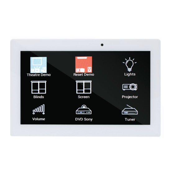
Page 22: Lecture Theatre Setup
This makes it ideal for any number of applications, including in the case of the Lecture Theatre example being used to configure the theatre when someone enters the room. Redback® Proudly Made In Australia www.redbackaudio.com.au... -
Page 23: System Wiring
6.2 Serial wiring RS232 Serial wiring from the Redback® A 6505A Serial Hub to the Redback® A 6510 or the Redback® A 6515 The RS232 control cabling requires only two connections from the output of the A 6505A Serial Hub to the input connec- tor of the A 6510 or A 6515. -
Page 24: Specifications
Current Draw: ..........30mA (idle) ..........80mA (Max) Dimensions: ........90W x 131D x 30H Weight: ..............0.19kg Current Draw: ..........50mA (idle) ..........150mA (Max) Weight: ..............0.18kg * Specifications subject to change without notice Redback® Proudly Made In Australia www.redbackaudio.com.au...
Need help?
Do you have a question about the A 6531 and is the answer not in the manual?
Questions and answers