Table of Contents
Advertisement
A 2078B Remote Plate
A 4578 Remote Plate
Please read these instructions carefully from front to back prior to installation.
Failure to follow these instructions may prevent the unit from working as designed.
www.redbackaudio.com.au
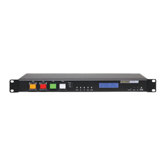
Redback® A 4500B Evacuation Controller & Timer
A 4500B
Alert/Evacuation Controller and 50 Event Timer
A 2078B
A 2081
Alert/Evac/Chime/Cancel Remote Wall Plate (Hard Wired)
A 4578
A 4581
Alert/Evac/Chime/Cancel Remote Wall Pl
A 4581V
Alert/Evac/Chime/Cancel Remote Wall Pl
A 4564
Emergency Paging Microphone Console (U/UTP Cat5)
A 2081 Remote Plate
A 4581 Remote Plate
Phone: 1300 780 999 Fax: 1300 790 999 Internet: www.altronics.com.au
IMPORTANT NOTE:
They include important setup instructions.
Operating Manual
Alert/Evac/Cancel Remote Wall Plate (Hard Wired)
Alert/Evac/Cancel Remote Wall Plate (U/UTP Cat5)
A 4581V Remote Plate
User manual revision number: 1.0 28/08/2020
Distributed by Altronic Distributors Pty. Ltd.
Redback® Proudly Made In Australia
Optional Accessories
ate
(U/UTP Cat5)
ate
(U/UTP Cat5)
A 4564 Paging Console
1
Advertisement
Table of Contents

Related Manuals for Redback A 4500B


Summary of Contents for Redback A 4500B
- Page 1 Redback® A 4500B Evacuation Controller & Timer Operating Manual A 4500B Alert/Evacuation Controller and 50 Event Timer Optional Accessories A 2078B Alert/Evac/Cancel Remote Wall Plate (Hard Wired) A 2081 Alert/Evac/Chime/Cancel Remote Wall Plate (Hard Wired) A 4578 Alert/Evac/Cancel Remote Wall Plate (U/UTP Cat5)
- Page 2 Australian Made Status All Redback house products made by Altronics will now be sporting the official Australian Made logo. Since starting manu- facturing of commercial audio equipment in the mid 70’s we have always taken pride in producing a quality local product.
-
Page 3: Table Of Contents
Redback® A 4500B Evacuation Controller & Timer CONTENTS 1.0 Overview Page 1.1 Introduction 1.2 Features 1.3 What’s in the box 1.4 Front panel guide 1.5 Rear panel connections 2.0 Setup 2.1 Initial Setup 2.2 Alert, Evac and Bell Switches 2.3 Programming the timing events using the front buttons 2.4 Programming the timing events using the supplied PC software... -
Page 4: Introduction
1.1 INTRODUCTION The A 4500B is a weekly timer and Evacuation controller all housed in a convenient 1RU rack mount chassis. A total of 50 “event” switching times are available through the timing functions. Each event can be set to turn on any single day of the week or on multiple days, from 1 sec up to 24 hours. -
Page 5: Front Panel Guide
Redback® A 4500B Evacuation Controller & Timer Overview 1.4 FRONT PANEL GUIDE Figure 1.4 shows the layout of the A 4500B front panel. 9 10 11 Alert Evac Bell Cancel A 4500 A 4500B 24 Hour 7 Day Timer 24 Hour 7 Day Timer... -
Page 6: Rear Panel Connections
Redback® A 4500B Evacuation Controller & Timer Overview 1.5 REAR PANEL CONNECTIONS Figure 1.5A shows the layout of the A 4500B rear panel. 8 9 10 11 12 13 Common Evac Alert Bell IMPORTANT NOTE 24V Out 24V Out 24V Out... - Page 7 Redback® A 4500B Evacuation Controller & Timer Overview Audio Out RCA Connectors Connect these outputs to the input of the background music amplifier. Bell Contact These contacts are for remote triggering of the Bell tone. These could be triggered by a remote switch or other closing contact.
-
Page 8: Setup
SD slot is not available then the Altronics D 0371B USB Memory Card Reader or similar would be suitable (not supplied). You will first need to remove power from the A 4500B and then remove the Micro SD card from the front of the unit. - Page 9 The A 4500B can now be switched back On. If all the MP3 files are OK then the unit will display the time screen. If an MP3 error message is is displayed, there is a problem with one or more of the MP3 files.
-
Page 10: Alert, Evac And Bell Switches
Redback® A 4500B Evacuation Controller & Timer Setup 2.2 ALERT, EVAC AND BELL SWITCHES The Alert, Evac and Bell switches on the front of the unit all work in momentary mode. ie. The alert tone will continue to sound after the alert switch is momentarily pressed and the evac tone will continue to sound after the evac switch is mo- mentarily pressed. - Page 11 “Output MP3”. The top left text is the time event number. Up to 50 events can be programmed into the A 4500B. Pressing the “up” and “down” buttons at this stage will move up and down through the events 1- 50. The top right text indicates that TIME1 (Event1) is currently disabled.
-
Page 12: Programming The Timing Events Using The Supplied Pc Software
Reader or similar would be suitable (not supplied). You will first need to remove power from the A 4500B and then remove the Micro SD card from the rear of the unit. To remove the Micro SD card push the card in and it will eject itself. - Page 13 All 50 events can be accessed on the screen by scrolling up and down. If you previously saved some timing information using the buttons on the A 4500B then these times should be displayed. Otherwise the timing information should all be blank as shown.
- Page 14 Redback® A 4500B Evacuation Controller & Timer Setup Fig 2.14 An event can now be programmed from this window. A description of the event can be added if desired such as Pre bell, Morning Tea etc. The start time, finish time, output and days of the week can all be entered. Selecting the days of the week is as simple as clicking the desired days or selecting the weekdays box.
- Page 15 Redback® A 4500B Evacuation Controller & Timer Setup The event should now appear in the programming window as shown in fig 2.16. Fig 2.16 Another event is now added by following the same steps. Double click on a blank line and then enter the details required as illustrated in fig 2.17.
-
Page 16: Setting The Current Time
With the events now programmed on the Micro SD card, the card can be removed from the PC following windows safe card removal procedures. Make sure the A 4500B is OFF and insert the Micro SD card into the slot in the front; it will click when fully inserted. -
Page 17: Deleting A Programmed Time
Redback® A 4500B Evacuation Controller & Timer Setup EDITING CLOCK 00:00:00 Fig 2.20 The cursor will be positioned over the hour section of the time. Use the up and down buttons to change the hour and then press the “Enter Button” to confirm the hour. The cursor will move to the minutes section of the time. Use the up and down buttons to change the minutes and then repeat the process again for the seconds. -
Page 18: Setting Alert To Evac Change-Over Times
Redback® A 4500B Evacuation Controller & Timer Setup 2.8 EV CHANGEOVER ress the “Menu” button on the front of the timer. The unit is now in “Menu Mode” and the screen should display the “Times Adjust” Screen. This is the first of 5 sub menu screens which are navigated by pressing the up and down buttons as shown in Fig 2.19. -
Page 19: Dip Switch Settings
Redback® A 4500B Evacuation Controller & Timer Setup 2.10 DIP SWITCH SETTINGS The A 4500B has various options which are set by the DIP switches on the rear of the unit. These are outlined below and in figures 2.24 and 2.25. IMPORTANT NOTE: Ensure power is switched off when adjusting DIP switches. -
Page 20: Remote Wall Plates
While the A 2081 wall plate provides a remote means of triggering the Alert, Evacuation and Bell tones and the cancel function. Connection from the A 2078B is made to the A 4500B via a minimum of 6 wires as shown in Fig 3.1A. Connec- tion is made from the A 2081 to the A 4500B via a minimum of 8 wires as shown in Fig 3.1B. -
Page 21: A 4578, A 4581 An A 4581V Remote Plates
“flip up” covers to prevent accidental operation. Connection is made to the A 4500B via standard Cat5e cabling as shown in Fig 3.2 There are two RJ45 ports on the rear of the wall plates, either of which can be used. Only one A 4578, A 4581 or A 4581V wall plate is allowed to be connected to the A 4500B via the “To Wall Plate”... -
Page 22: Paging Console
Provision has been made for the connection of one only paging console which is wired back to the A 4500B via CAT5E cabling to the RJ45 “To Paging Console” port on the rear of the A 4500B (see figure 4.1 for details). -
Page 23: Troubleshooting
Redback® A 4500B Evacuation Controller & Timer Troubleshooting 5.0 TROUBLE SHOOTING 5.1 SYMPTOMS AND REMEDIES SYMPTOMS REMEDIES PC SOFTWARE WILL NOT RUN The PC software for this product may not run on all PC’s. The .NET framework on the PC has to be updated to .NET Framework 4. -
Page 24: Firmware Update
To perform an update, follow these steps. 1) Download the Zip file from the website. 2) Remove the Micro SD card from the A 4500B and insert it into your PC. (Follow the steps on page 8 to open the Micro SD card).
Need help?
Do you have a question about the A 4500B and is the answer not in the manual?
Questions and answers