Table of Contents
Advertisement
Quick Links
Redback® A 4595A School Lockdown Controller
Optional Accessories
A 4596 Paging Console
A 4597 Remote Plate
A 4598 Remote Plate
A 4598V Remote Plate
Operating Manual
A 4595A School Lockdown Controller
A 4596 Paging Console
A 4597 Fire Test Remote Wallplate
A 4598 Lockdown Remote Wallplate (Horizontal)
A 4598V Lockdown Remote Wallplate (Vertical)
Redback® Proudly Made In Australia
Distributed by Altronic Distributors Pty. Ltd.
Phone: 1300 780 999 Fax: 1300 790 999 Internet: www.altronics.com.au
IMPORTANT NOTE:
Please read these instructions carefully from front to back prior to installation.
They include important setup instructions.
Failure to follow these instructions may prevent the amplifier from working as designed.
Please check www.altronics.com.au for the latest revisions of instruction manuals.
User manual revision number: 1.0 06/05/2020
www.altronics.com.au
Redback® Proudly Made In Australia
1
Advertisement
Table of Contents

Related Manuals for Redback A 4595A


Summary of Contents for Redback A 4595A
- Page 1 Redback® A 4595A School Lockdown Controller Optional Accessories A 4596 Paging Console A 4597 Remote Plate A 4598 Remote Plate A 4598V Remote Plate Operating Manual A 4595A School Lockdown Controller A 4596 Paging Console A 4597 Fire Test Remote Wallplate...
- Page 2 Australian Made Status All Redback house products made by Altronics will now be sporting the official Australian Made logo. Since starting manufacturing of commercial audio equipment in the mid 70’s we have always taken pride in producing a quality local product.
-
Page 3: Table Of Contents
Redback® A 4595A School Lockdown Controller CONTENTS 1.0 Overview 1.1 Introduction 1.2 Features 1.3 What’s in the box 1.4 Front panel guide 1.5 Rear panel connections 2.0 Operation 2.1 Lockdown Modes 2.2 Fire Test/Fire Alarm 2.3 Prebell/Bell 2.4 Auxilliary MP3 Triggers 2.5 Priorities... -
Page 4: Overview
The lockdown unit can be connected to the A 4565 alert/evac controller if an EWIS system is also required and is made with a dual RCA lead . The A 4565 will take priority over the A 4595A lockdown unit in the case of an emergency. -
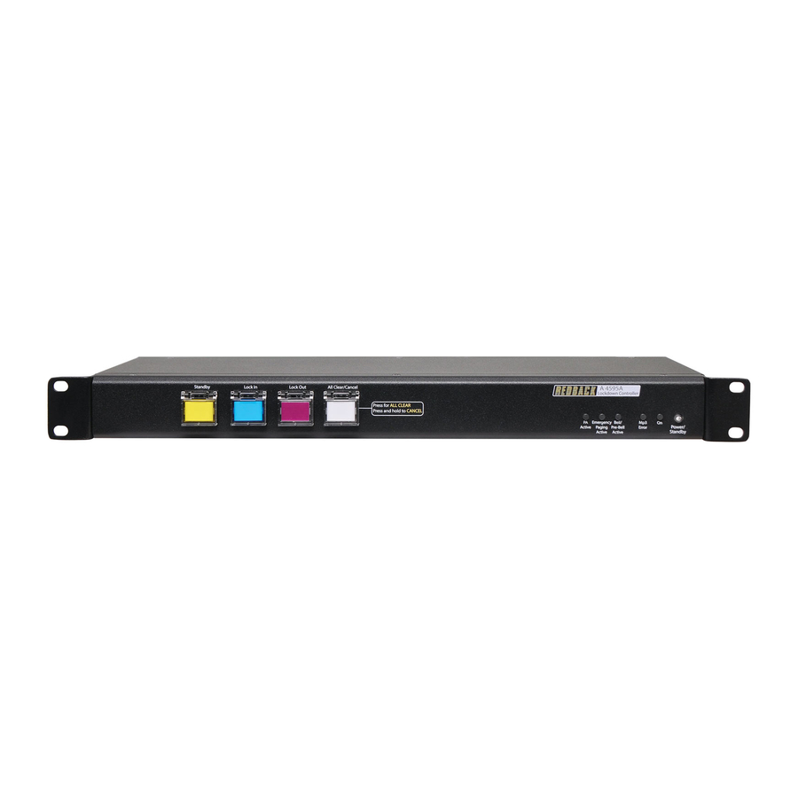
Page 5: Front Panel Guide
Redback® A 4595A School Lockdown Controller 1.4 FRONT PANEL GUIDE Fig 1.4A shows the layout of the A 4595A front panel. 8 9 10 Standby Lock In Lock Out All Clear/Cancel A 4595A Lockdown Controller Press for ALL CLEAR Press and hold to CANCEL... -
Page 6: Rear Panel Connections
Redback® A 4595A School Lockdown Controller 1.5 REAR PANEL CONNECTIONS Fig 1.5A shows the layout of the A 4595A rear panel. 10 11 12 All Clear Lock In Standby Lock Out Bell/Pre-Bell Common Emergency DIP Switch Settings IMPORTANT NOTE Contacts... - Page 7 Redback® A 4595A School Lockdown Controller Audio Out RCA Connectors Connect these outputs to the input of the PA amplifier. RJ45 connector This RJ45 ports is for future peripheral devices. RJ45 connector This RJ45 ports is for future peripheral devices.
-
Page 8: Operation
These are triggered by closing contact terminals on the rear of the unit. Once the Aux MP3’s are activated an MP3 audio file is played until the audio file finishes or the A 4595A changes mode. -
Page 9: Priorities
■ Fire Test, PreBell/Bell Tone ,AuxMP3-1, AuxMP3-2, AuxMP3-3 These triggers have the lowest priority of all functons on the A 4595A are can be overridden by every other function. The Fire test can only be initiated by the Fire Test wall plate (A 4597). -
Page 10: Audio Connections
These contacts are for operating an external relay used to operate something like a school bell. Fig 3.3 demonstrates an example of how to connect the A 4595A Lockdown Controller to the Altronics A 1708 timer to trigger the schools Pre-Bell and Bell . - Page 11 Redback® A 4595A School Lockdown Controller Lock In 24V Out: These contacts are for switched 24V outputs whenever the LockIn mode is activated. These may be used to run external systems such as strobes in unusually noisy environments or for hearing impaired students or staff. They may also be used for the connection of override relays in remote volume controls.
-
Page 12: Micro Sd Card (Mp3)
NOTE: It is recommended to store only one MP3 file in each folder. The A 4595A will play the first file it finds in each folder which corresponds to the mode the unit is running in. For example if “Standby Mode” is activated, the A 4595A will search the “Standby” folder on the Micro SD card, and then play the corresponding MP3 file. - Page 13 Redback® A 4595A School Lockdown Controller all clear folder Fig 3.4b • Open the allclear folder and inside you should find an MP3 audio file as shown in Fig 3.4c. Delete this file and copy your own MP3 file to this folder as shown in fig 3.4d (NOTE : The audio file must be in MP3 format). The file can be named anything you like as long as it is in MP3 format (iin this case we have named it New_allclear_tone).
- Page 14 Once complete, remove the SD card from the PC, following Windows safe card removal procedures. Make sure the A 4595A is OFF and then insert the SD card back into the rear of the unit. The SD card holder will click when the SD card is inserted correctly.
-
Page 15: Connecting To The A 4565
The output of the A 4595A Lockdown controller is connected to the Audio In Input of the A 4565 using dual RCA leads. The output volume is set by the Master volume trimpot adjustment on the rear of the A 4595A. The output of the A 4565 is then fed into the buildings PA system. -
Page 16: Connecting To The A 4565 And The A 4585
Alert/Evacuation Controller and the A 4580 16 Zone Paging System. In order to allow the A 4595A and the A 4565 to be fed through the paging system, the wiring diagram shown in Fig 3.6 must be followed. The audio output of the A 4595A is fed into the BGM (background music input) of the A 4565. The Audio output of the A 4565 is then fed into the Evac input of the A 4580. -
Page 17: Paging Consoles
The four Lock Down modes can all be activated from the A 4596 paging console. Simply Press the button for the desired mode and hold for 2-3 seconds to activate. The priorities for these are the same as on the main A 4595A unit. I.e All Clear overrides Lock Down and Lock In, which have the same priority, which then overrides Standby. - Page 18 Set the DIP switches 3-4 select the ID number for the console. Console ID Fig 4.1b shows the ID settings. A maximum number of 4 consoles can be connected to the A 4595A. On O On On IMPORTANT NOTE: Ensure power is switched off when adjusting DIP switches.
- Page 19 The consoles are connected to the A 4595A via standard Cat5e cabling as shown in Fig 4.1c. The maximum distance between the A 4595A and a paging console is 300m. Note that each paging console must be assigned an ID number before operation (see 4.1.2 DIP switch settings).
-
Page 20: A 4598 And A 4598V Overview
Connection is made to the A 4595A via standard Cat5e cabling as shown in figure 4.2B. There are two RJ45 ports on the rear of the A 4598 and A 4598V wall plates, either of which can be used. - Page 21 Redback recommends a combined maximum of CAT5e cable CAT5e cable 16 x (A 4598, A 4598V or A 4597) wall plates be connected to the A 4595A as shown in this gure. Lock In Lock Out Lock In Lock Out...
-
Page 22: A 4597 Overview
“flip up” covers to prevent accidental operation. Connection is made to the A 4595A via standard Cat5e cabling as shown in Fig 4.2C. There are two RJ45 ports on the rear of the A 4597 wall plate, either of which can be used. These are connected in the same manner as the A 4598 wall plates, and can be daisy chained in line with the A 4598 plates. -
Page 23: Troubleshooting
Redback® A 4595A School Lockdown Controller 5.0 TROUBLE SHOOTING 5.1 SYMPTOMS AND REMEDIES SYMPTOMS REMEDIES Front switches not responding Press and hold switch for at least 2 seconds Output Volume Level Is Low Adjust master volume on rear of unit... -
Page 24: Specifications
Redback® A 4595A School Lockdown Controller 6.0 SPECIFICATIONS OUTPUT LEVEL:.........0dBm into 600Ω OUTPUT CONNECTORS: Audio Output:......RCA Stereo Socket Emergency 24V DC Out:.....Euroblock terminal Common 24V DC Out :....Euroblock terminal Prebell/Bell 24V DC Out:....Euroblock terminal Standby 24V DC Out:....Euroblock terminal Lock In 24V DC Out:....Euroblock terminal Lock Out 24V DC Out:....Euroblock terminal...
Need help?
Do you have a question about the A 4595A and is the answer not in the manual?
Questions and answers