Table of Contents
Advertisement
Advertisement
Table of Contents

Subscribe to Our Youtube Channel
Related Manuals for Alvarado SU5000


Summary of Contents for Alvarado SU5000
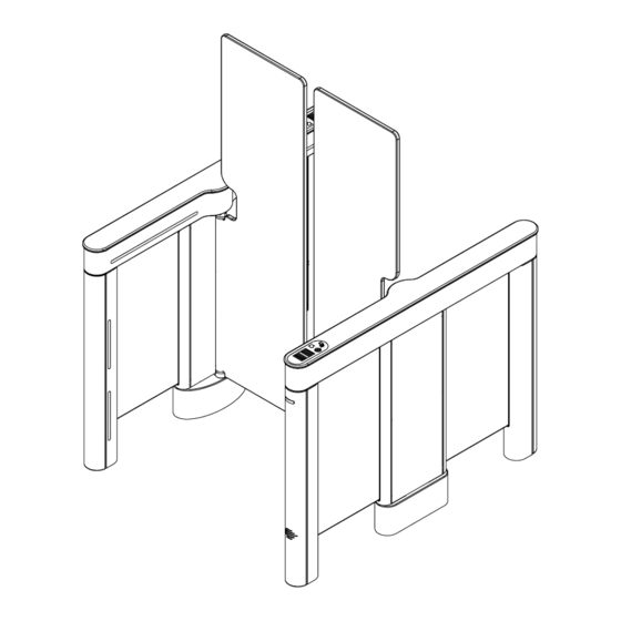
- Page 1 SUPERVISOR 5000 (SU5000) Optical Turnstile with Bi-directional Motorized Barriers Installation Instructions Alvarado Manufacturing Company, Inc. 12660 Colony Street, Chino, CA 91710 Phone: +1 (909) 591-8431 Fax: +1 (909) 628-1403 support@alvaradomfg.com www.alvaradomfg.com PUD3667R1-6...
-
Page 2: Table Of Contents
Supervisor 5000 Installation Instructions Contents Contents..................................2 ETL Certification................................2 Safety Precautions................................3 Safety Icons..................................3 Installation Tools................................4 Uncrating..................................4 Parts List..................................4 Introduction..................................6 Before You Begin................................8 Slab Requirements..............................8 Space Requirements. -
Page 3: Safety Precautions
De plus, bien former les nouveaux utilisateurs à leur intégration au système. • NE PAS utiliser des pièces ne provenant pas du Alvarado pour réparer un tourniquet endommagé. • Suivez strictement les instructions de manutention pour déplacer ou soulever le tourniquet lors de l'installation •... -
Page 4: Installation Tools
Clear RTV Silicone Uncrating The SU5000 has been packed for shipping to prevent damage to the unit. Two or more installers are required to unload the SU5000 at the installation site. Once the turnstile cabinets have been placed in the installation location, carefully remove the protective packing material from the sides of the cabinets. - Page 5 Supervisor 5000 Installation Instructions Parts List (cont.) Center Cabinets are used to create additional lanes for multi-lane configurations. Each additional lane includes the parts below. Center Cabinet Parts List (Per Center Cabinet) End Covers Barriers Center Cabinet (Qty 2) (Qty 2) (Qty 1) NOTE (Barrier height and width may vary.)
-
Page 6: Introduction
This manual covers the physical installation process for SU5000 Optical Turnstiles. A separate SU5000 User Guide provides operating instructions and additional information such as configuring turnstiles for bi-directional passage applications and monitoring outputs. It is highly recommended that both this manual and the SU5000 User Guide be read in their entirety prior to beginning installation. - Page 7 Dry Contact Single passage activation and the various other inputs and outputs available to / from the SU5000 are accessed through the I/O control board located in the master cabinet. The required system input is a voltage-free, momentary dry contact. Outputs are also provided in this form.
-
Page 8: Before You Begin
Supervisor 5000 Installation Instructions Before You Begin Use only skilled technicians for site preparation and installation of the turnstile using Alvarado’s instructions. Slab Requirements The following slab requirements must be taken into consideration when selecting the installation location: • A level solid concrete pad with a minimum thickness of 4" (102mm). -
Page 9: Conduit Requirements
DO NOT install the product outdoors. This product is intended for indoor use only. • DO NOT install the SU5000 where infrared lighting (strobe lights, flash photography, etc.) is in the direct path of the optical sensors. Interference may affect the performance of the turnstile. -
Page 10: Communication Requirements
MDC’s must be at least 100ms in duration to register. While the SU5000 can accept signals up to 2 seconds in duration, the suggested MDC input duration is 1 second or less to support rapid throughput in high volume applications. -
Page 11: Pre-Installation Instructions
Supervisor 5000 Installation Instructions Pre-Installation Instructions NOTE It is assumed that the Pre-Installation Checklist steps are complete. Cabinet Panel Removal Fig. 6 Removing Screws Using a Phillips screwdriver, remove the six (6) mounting screws that secure the cabinet panel to the master cabinet [Figure 6]. -
Page 12: Baseplate Installation (Optional)
Refer to Appendix C on Page 34 for 28" and 36" baseplate dimensions. The baseplate enables installation of the SU5000 turnstile on a solid foundation without the need to drill holes into the concrete. The baseplate also provides concealed conduit channels for wiring primary power, crossover communication, and access control. -
Page 13: Installation Instructions
Supervisor 5000 Installation Instructions Installation Instructions Anchoring the Turnstile NOTE The lane 1 master cabinet is always the right-most cabinet in relation to the unsecured side. Place the master cabinet and the slave cabinet in the determined location [see dimensions - Figure 4]. All cabinets must be level and square to eachother. -
Page 14: End Cover Installation
(7 total) End Cover Installation Fig. 12 Installing End Covers The end covers are shipped loosely attached to the SU5000 with the mounting hardware taped inside each cover. LOWER END NOTE If installing an end cover that has a barcode reader installed, be sure to connect the barcode reader communication cable to your access control board before installing the end cover. -
Page 15: Internal Card Reader Installation
SU5000 power supply. Board Due to the slim design of the SU5000, there is no space available to install circuit boards or other equipment associated with the access control system. Access control boards used in connection with the... -
Page 16: Wiring Instructions
Fig. 18 and low-voltage 24VDC between the master and slave cabinets. The default length of the crossover cable included with the SU5000 is 8'. Optional crossover cable lengths of 20' and 40' are available. Locate the low-voltage terminal block tucked in the bottom of the base in the master cabinet [Figure 18]. -
Page 17: I/O Control Board (13-0328 Rev. F)
Master Cabinet To / From Access Control System Inputs Signal inputs from outside systems are wired into the SU5000’s I/O control board. There are two types of input signals, momentary dry contacts (MDC) and sustained dry contacts (SDC). All input signals must be normally open (N.O.), voltage-free, dry contacts, with... - Page 18 Common output signal Ground Common input ground signal. ground. Door Held An output occurs when the Normally Not available on the SU5000. Open barriers remain open after Open Mode the allotted time to close after passage (default 12 seconds). BREAKAWAY...
-
Page 19: Configuring Passage Modes
For example, a turnstile can be configured for Controlled Passage mode in the entry direction, and Free Passage mode in the exit direction. SU5000 passage modes are described on Page 23. Further information on the smart use of passage modes can be found in the SU5000 User Guide. - Page 20 Supervisor 5000 Installation Instructions Setting Free Passage Mode (I/O Control Board) Fig. 21 Entry Direction Locate the ENTPAS and GND Entry Direction terminals. Using a wire jumper, connect the ENTPAS and GND terminals [Figure 21]. Exit Direction Exit Direction Locate the EXTPAS and GND terminals.
-
Page 21: Ethernet Communication (Optional)
Supervisor 5000 Installation Instructions Ethernet Communication (Optional) Fig. 23 I/O Control Board NOTE It is assumed that Ethernet cabling has been run to the turnstile via conduit and pulled through the conduit opening in Step 6 of the Anchoring the Turnstile section. Locate the Ethernet extension cable tucked in the base of the master/center cabinet [Figure 23]. - Page 22 Supervisor 5000 Installation Instructions Barrier Installation (cont.) Tightening Mounting Fig. 25 Position the clamp bar on the barrier. Insert and tighten the Screws mounting screws and clamp bar to 44 in-lbs. Test to make sure the barrier does not wiggle [Figure 25]. Clamp Bar Fig.
-
Page 23: Post-Installation Functions Check
Troubleshooting section on Page 31. Passage Modes Before beginning the Post-Installation Functions Check, please read the following brief descriptions of the three SU5000 passage modes. More information on SU5000 passage modes can be found in the SU5000 User Guide. - Page 24 Supervisor 5000 Installation Instructions Testing Turnstile Functionality Perform the following turnstile functionality tests to validate basic turnstile operation. Tests are provided for Controlled Passage, Free Passage, and No Passage modes. The following is assumed (Controlled Passage mode tests only): • The access control system is operational and all access control wiring to the turnstile is connected.
- Page 25 Supervisor 5000 Installation Instructions Testing Turnstile Functionality (cont.) FREE PASSAGE MODE Enter the turnstile and complete a passage. • User Status Light green arrow is Free Passage flashing. Entry / Exit • Barriers open away from the user Secured Side entering the turnstile.
- Page 26 Supervisor 5000 Installation Instructions Testing Lane Key Control (Optional) Fig. 28 Lane Key Control Switch Locations Optional 3-position lane key control switches can be selected during the ordering process. Lane key control switches are used Secured Side to change passage modes for both directions of travel. Two (2) Lane lane key control switches are installed per turnstile in the bottom end legs as shown in [Figure 28].
- Page 27 Supervisor 5000 Installation Instructions Testing Ethernet Communication (Optional) NOTE The following procedure is applicable to non-networked (standalone) turnstiles. For instructions on testing Ethernet communication over a facility network, please refer to the SU5000 User Guide. Required Items: • CAT5/6 Ethernet Cable •...
-
Page 28: Finish The Installation
Supervisor 5000 Installation Instructions Finish the Installation Cabinet Lid Installation NOTE Due to limited access, use the M4 Allen 'stubby' wrench provided. (The wrench is taped to the underside of all end cabinet lids.) Lower the lid onto the cabinet housing [Figure 32]. WARNING Do not force the lid into place. -
Page 29: Cabinet Panel Installation
Supervisor 5000 Installation Instructions Cabinet Panel Installation Fig. 33 Cabinet Panel Installation Orient the cabinet panel so the sensor windows are at the bottom and gently slide the cabinet panel into position. Using a Phillips screwdriver, insert and tighten the six (6) mounting screws that secure the cabinet panel to the cabinet [Figure 33]. -
Page 30: Post-Installation Checklist
(see SU5000 User Guide). Powder Coated - Wipe down power coated surfaces with a damp cloth. Manuals Handoff Provide both these SU5000 Installation Instructions and the SU5000 User Guide to the project or site manager. Page 30 For assistance: support@alvaradomfg.com +1 (909) 591-8431... -
Page 31: Troubleshooting
Locate the motor controller board fuses [Figure 36]. Using a multimeter, check the boot. board fuse is 5VDC 3A and 12VDC 2A fuses for continuity. If a fuse is blown, contact Alvarado for a blown. replacement. NOTES: If a user status display or open / closed status light is out, this may indicate the 5VDC 3A fuse is blown. -
Page 32: Appendix A - Setting The Home Position
Supervisor 5000 Installation Instructions Appendix A - Setting the Home Position Fig. A1 Master Cabinet - Motor Controller Board Locate the motor controller board in the master or center cabinet [Figure A1 or A2] respectively. The (D2) LED will be blinking indicating normal operation mode. -
Page 33: Appendix B - 36" Single Lane - Plan, Elevation & Footprint Drawing
Supervisor 5000 Installation Instructions Appendix B - 36" Single Lane - Plan, Elevation & Footprint Drawing Plan View 47.0 (1194) 17.0 (51) (432) 52.4 (1331) 36.0 (914) Elevation View 43.0 (1092) 41.0 35.0 (889) (1041) 6.0 (152) Footprint (48) (23) (33) (33) (18) -
Page 34: Appendix C - 28" & 36" Baseplate Dimensions
Supervisor 5000 Installation Instructions Appendix C - 28" & 36" Baseplate Dimensions Fig. C1 28" Baseplate Dimensions 52.5 [1333.5] 40.8 [1036.5] Fig. C2 36" Baseplate Dimensions 52.5 [1333.5] 48.8 [1239.7] Page 34 For assistance: support@alvaradomfg.com +1 (909) 591-8431 PUD3667R1-6... -
Page 35: Appendix D - External Dc Power Supply Installation (Optional)
One power supply is required per lane. Each power supply enclosure can house up to three power supplies. The power supplies are pre-installed at Alvarado prior to shipping. Make sure to locate all required components, and verify the correct number of power supplies are present prior to beginning installation. - Page 36 Supervisor 5000 Installation Instructions Connect Primary Power to Enclosure(s) Fig. D3 Primary Power Terminal Block NOTE Primary power wiring and connectors are not supplied by Alvarado. Conduit Hole The primary wiring lines for 110VAC and 220VAC consist of the following: Terminal...
- Page 37 If you do not require all twelve connectors, only use what is needed. Due to the differences of each installation scenario, 24VDC wire is not supplied by Alvarado. See the recommendations below for selecting the best wire for your installation.
- Page 38 Supervisor 5000 Installation Instructions External DC Power Supply Connection Diagram Fig. D6 Connection Diagram TO CIRCUIT BREAKER 110VAC / 220VAC INPUT POWER SUPPLY ENCLOSURE 24VDC OUTPUT LANE 3 LANE 2 LANE 1 Page 38 For assistance: support@alvaradomfg.com +1 (909) 591-8431 PUD3667R1-6...
- Page 39 Supervisor 5000 Installation Instructions Power Supply Enclosure Dimensions Fig. D7 Dimensions 15.80[401.4] 9.50[241.3] 6.23[158.1] 110 / 220VAC 24VDC CONDUIT HOLE CONDUIT HOLES PUD3667R1-6 For assistance: support@alvaradomfg.com +1 (909) 591-8431 Page 39...
-
Page 40: Appendix E - Multi-Lane Conduit Requirements
Supervisor 5000 Installation Instructions Appendix E - Multi-Lane Conduit Requirements Two-Lane Configuration LANE 2 LANE 1 Slave Cabinet Center Cabinet Master Cabinet Three-Lane Configuration LANE 3 LANE 2 LANE 1 Slave Cabinet Center Cabinet Center Cabinet Master Cabinet Symbology Description Conduit Size Primary 3/4”... -
Page 41: Appendix F - Crossover Cable Connection Diagrams
Supervisor 5000 Installation Instructions Appendix F - Crossover Cable Connection Diagrams One-Lane Configuration SLAVE MASTER Master Cabinet Slave Cabinet Two-Lane Configuration LANE 1 LANE 2 SLAVE MASTER SLAVE MASTER Center Cabinet Master Cabinet Slave Cabinet Three-Lane Configuration LANE 2 LANE 3 LANE 1 SLAVE MASTER... -
Page 42: Revision History
Supervisor 5000 Installation Instructions Revision History Revision Date Author Description 07/14/14 A. Flores Initial creation. Replaces SU5000 Installation and Operation Instructions (PUD3297R2-6). 10/29/14 A. Flores Added Baseplate installation instructions. 04/30/15 A. Flores Added instructions for leveling cabinets and checking barriers for straightness. - Page 43 This page intentionally left blank. Installation Instructions Page 43 support@alvaradomfg.com +1 (909) 591-8431 www.alvaradomfg.com...
Need help?
Do you have a question about the SU5000 and is the answer not in the manual?
Questions and answers