Table of Contents
Advertisement
Quick Links
Advertisement
Table of Contents

Related Manuals for PR electronics 4222


Summary of Contents for PR electronics 4222
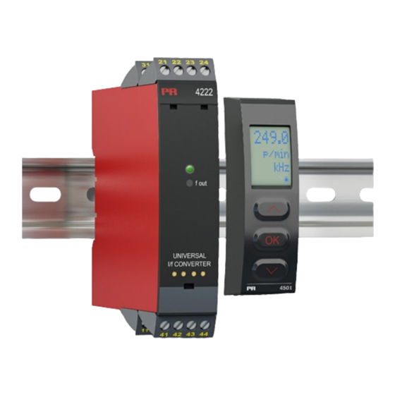
- Page 1 PERFORMANCE MADE SMARTER Product manual 4222 Universal I/f converter T E M P E R AT U R E I . S . I N T E R FA C E S CO M M U N I C AT I O N I N T E R FA C E S...
- Page 2 6 Product Pillars to meet your every need Individually outstanding, unrivalled in combination With our innovative, patented technologies, we make signal conditioning smarter and simpler. Our portfolio is composed of six product areas, where we offer a wide range of analog and digital devices covering over a thousand applications in industrial and factory automation.
-
Page 3: Table Of Contents
Universal I/f converter 4222 Table of contents Warning .................... -
Page 4: Warning
HAZARD- Troubleshooting the device. VOLTAGE Repair of the device and replacement of circuit breakers must be done by PR electronics A/S only. CAUTION Warning Do not open the front plate of the device as this will cause damage to the connector for the display / programming front PR 4500. - Page 5 Should there be any doubt as to the correct handling of the device, please contact your local distributor or, alternatively, PR electronics A/S www.prelectronics.com Mounting and connection of the device should comply with national legislation for mounting of electric materials, i.e. wire cross section, protective fuse, and location.
-
Page 6: How To Demount System 4000
How to demount system 4000 First, remember to demount the connectors with hazardous voltages. Picture 1: The device is detached from the DIN rail by moving the bottom lock down. 4222V102-UK... -
Page 7: Application
When 4222 is used in combination with the PR 4500 display / programming units, all operational parameters can be modified to suit any application. As the 4222 is designed with electronic hardware switches, it is not necessary to open the device for setting of DIP-switches. -
Page 8: Applications
Applications Input signals: Volt - Potentio- meter Current RTD and lin.R Connect., wires Output signals: Frequency output PNP, +24 V NPN, 24 V Out., Gnd TTL, 5 V Supply: 21.6...253 VAC 19.2...300 VDC 4222V102-UK... -
Page 9: Pr 4500 Display / Programming Front
Application • Communications interface for modification of operational parameters in 4222. • Can be moved from one 4222 device to another and download the configuration of the first unit to subsequent units. • Fixed display for readout of process data and status. -
Page 10: Order
Order 4222 = Universal I/f converter Accessories 4501 = Display / programming front 4511 = Modbus communication enabler 4512 = Bluetooth communication enabler Electrical specifications Environmental conditions Operating temperature ....... . -20°C to +60°C Storage temperature . - Page 11 Accuracy, the greater of general and basic values: General values Input type Absolute accuracy Temperature coefficient ≤ ±0.1% of span ≤ ±0.01% of span / °C Basic values Type Basic accuracy Temperature coefficient ≤ ±4 µA ≤ ±0.4 µA / °C ≤...
- Page 12 TC input Min. Max. Type Standard value value +400°C +1820°C IEC 60584-1 -100°C +1000°C IEC 60584-1 -100°C +1200°C IEC 60584-1 -180°C +1372°C IEC 60584-1 DIN 43710 -200°C +900°C -180°C +1300°C IEC 60584-1 -50°C +1760°C IEC 60584-1 -50°C +1760°C IEC 60584-1 -200°C +400°C IEC 60584-1...
- Page 13 TTL output max........15 mA sink/source peak .
-
Page 14: Visualisation In The Pr 4500 Of Sensor Error Detection And Input Signal Outside Range
Visualisation in the PR 4500 of sensor error detection and input signal outside range Sensor error check: Device Configuration Sensor error detection: OUT.ERR=NO 4222 Else: Signal conditioning limits Outside range readout (IN.LO, IN.HI): If the valid range of the A/D converter or the polynomial is exceeded Input Range... -
Page 15: Error Indications
CJ.ER CJC sensor defect or temperature outside range Checksum test of the configuration in FLASH FL.CO Error in FLASH Communications test PR 4500 / 4222 NO.CO Connection error Check that input signal matches input IN.ER 1) Error levels on input... -
Page 16: Connections
Connections Supply Inputs: RTD, 2-wire RTD, 3- / 4-wire Resistance, 2-wire 41 42 41 42 41 42 Resistance, 3- / 4-wire Potentiometer 2-wire transmitter Current 41 42 41 42 41 42 41 42 Voltage 41 42 Outputs: 21 22 21 22 21 22 + 5 V + 24 V... -
Page 17: Block Diagram
Block diagram RTD and lin. R, Supply connection 21.6...253 VAC or wires 0.2 mA 19.2...300 VDC loop Supply Frequency generator PNP, 24 V Green 20 Ω EEPROM Yellow 50.0 l / min VALVE 5 Gnd. 4222 TTL, 5 V 4222V102-UK... -
Page 18: Configuration / Operating The Function Keys
In general When configuring the 4222, you will be guided through all parameters and you can choose the settings which fit the application. For each menu there is a scrolling help text which is automatically shown in line 3 on the display. - Page 19 Language (LANG): In the menu ”LANG” you can choose between 7 different language versions of help texts that will appear in the menu. You can choose between UK, DE, FR, IT, ES, SE and DK. Auto diagnosis The device performs an advanced auto diagnosis of the internal circuits. The following possible errors can by displayed in the front unit PR 4500.
-
Page 20: Routing Diagram
Routing diagram Power up If no key is activated for 1 minute, the display will return to the default state 1.0 without saving configuration changes. 1 Increase value / choose next parameter 2 Decrease value / choose previous parameter 3 Save the chosen value and proceed to the next menu Hold 3 Back to previous menu / return to menu 1.0 without saving. - Page 21 p / m p / h 999.9 50%DC p / d -199.9 25000 25000 25000 prg p 1000 100.0 25.00 DISP.HI OU.UN f.min f.max CUT.OFF O.TYPE t.PULSE Txt 14 Txt 20 Txt 21 Txt 22 Txt 23 Txt 19 Txt 24 f>500 Hz 50% DC 50%DC...
- Page 22 4172 4172 26250 -328 -328 To default OUT.ERR f.ERR RESP OUT.LO OUT.HI state 1.0 Txt 25 Txt 26 Txt 40 Txt 41 Txt 42 315000 OUT.ERR f.ERR Txt 25 Txt 26 1.2 = Not valid for these input signals: 0...20 mA and voltage.
-
Page 23: Routing Diagram, Advanced Settings (Adv.set)
Routing diagram, advanced settings (ADV.SET) DISP PASS 2.0 In the submenu simulation (SIM) you must press 3 SAVE LANG to return to the default state 1.0. LOAD LATC SAVE SETUP MEMORY Txt 43 Txt 44 f.OUT DISP f.OUT SETUP CONTRA LIGHT VALVE 5 LINE 3... -
Page 24: Help Text Overview
Help text overview [01] Set correct password Select TC-W5 as sensor type [02] Enter advanced setup menu? Select TC-Lr as sensor type [19] [03] Select temperature input Select 50% duty cycle output Select programmable pulse time Select potentiometer input [20] Select Hz as output unit Select linear resistance input Select pulses/minute as output unit... -
Page 25: Document History
Document history The following list provides notes concerning revisions of this document. Rev. ID Date Notes 0845 Initial release of the product. 1311 FM and EAC approvals added. 2135 UKCA added. 4222V102-UK... - Page 26 We are near you, all over the world Our trusted red boxes are supported wherever you are All our devices are backed by expert service and a 5-year business with a global reach. This means that we are warranty. With each product you purchase, you receive always nearby and know your local markets well.
- Page 27 Benefit today from PERFORMANCE MADE SMARTER PR electronics is the leading technology company specialized in making industrial process control safer, more reliable and more efficient. Since 1974, we have been dedicated to perfecting our core competence of innovating high precision technology with low power consumption.
Need help?
Do you have a question about the 4222 and is the answer not in the manual?
Questions and answers