Table of Contents
Advertisement
Quick Links
Product manual
3100
6 mm series of isolators
and converters
ZONE 2
Zone 2
T E M P E R AT U R E
|
I . S . I N T E R FA C E S
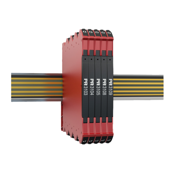
Models no. 3103 / 310 4 / 3105 / 310 8 / 310 9
No. 310 0V111- UK
ZONE 2 / DIV 2
|
CO M M U N I C AT I O N I N T E R FA C E S
|
M U LT I F U N C T I O N A L
|
I S O L AT I O N
PERFORMANCE
MADE
SMARTER
|
D I S P L AY
Advertisement
Table of Contents

Related Manuals for PR electronics 3100 Series


Summary of Contents for PR electronics 3100 Series
- Page 1 PERFORMANCE MADE SMARTER Product manual 3100 6 mm series of isolators and converters ZONE 2 Zone 2 ZONE 2 / DIV 2 T E M P E R AT U R E I . S . I N T E R FA C E S CO M M U N I C AT I O N I N T E R FA C E S M U LT I F U N C T I O N A L I S O L AT I O N...
- Page 2 6 Product Pillars to meet your every need Individually outstanding, unrivalled in combination With our innovative, patented technologies, we make signal conditioning smarter and simpler. Our portfolio is composed of six product areas, where we offer a wide range of analog and digital devices covering over a thousand applications in industrial and factory automation.
-
Page 3: Table Of Contents
6 mm series of isolators and converters 3103 / 3104 / 3105 / 3108 / 3109 Table of contents Warnings ....................Symbol identification . -
Page 4: Warnings
To avoid explosion and serious injury: Modules having mechanical failures must be returned to PR electronics for repair or replacement. Repair of the device and replacement of circuit breakers must be done by PR electronics A/S only. Until the device is fixed, do not connect hazardous voltages to the device. -
Page 5: Safety Instructions
Should there be any doubt as to the correct handling of the device, please contact your local distributor or, alternatively, PR electronics A/S www.prelectronics.com Mounting and connection of the device should comply with national legislation for mounting of electric materials, e.g. wire cross section, protective fuse, and location. -
Page 6: Mounting / Demounting Of System 3000
Mounting / demounting of system 3000 Mounting on DIN rail / power rail (Fig.1) Demounting from DIN rail / power rail (Fig.2) Click the device onto the rail First, remember to demount the connectors with hazardous voltages. Detach the device from the rail by moving the bottom lock down. -
Page 7: Installation On Din Rail / Power Rail
Installation on DIN rail / power rail System 3000 devices can be installed on a DIN rail or on a power rail. For marine applications, the devices must be supported by a module stop (PR part number 9404). Power supply units can be mounted on the power rail according to customer requirements. Marking The front cover of the 3000 devices has been designed with an area for affixation of a click-on marker. -
Page 8: Flexible Supply
Flexible supply The technical specifications specify the maximum required power at nominal operating values, e.g. 24 V supply voltage, 60°C ambient temperature, 600 Ω load, and 20 mA output current. External protective fuses may be required depending on power source selected. Protective fuse ratings are specified below. DIN rail solution - device daisy chain: Power rail solution #2: The units can be supplied with 24 VDC ±30%... -
Page 9: Applications
6 mm series of isolators and converters 3103 / 3104 / 3105 / 3108 / 3109 The product family 3103, 3104, 3105, 3108 & 3109 are slimline isolaters for 24 VDC fixed supply and can be used for different purposes. •... -
Page 10: Connections
Connections Input Output ch. 1 Output Supply ch. 2 Safe Area or Zone 2 & Cl. 1, Div. 2, gr. A-D Input signals 3103 3104 3105 3108 3109 Current Voltage Output signals 3103 3104 3105 3108 3109 Current 1 Voltage 1 Current 2 Voltage 2 Supply... -
Page 11: Product Overview
Product overview PR type no. 3103 3104 3105 PR product name Isolated repeater Isolated converter Isolated converter Description Fixed loop isolator / repeater. Loop isolator / converter for Loop isolator / converter for standard DC signals. standard DC signals. DIP-switch setup. DIP-switch setup. -
Page 12: Order
Order Type Version 3103 Isolated repeater With power rail connector / terminals Supplied via terminals : -N 3104 Isolated converter With power rail connector / terminals Supplied via terminals : -N 3105 Isolated converter With power rail connector / terminals Supplied via terminals : -N 3108... - Page 13 Common electrical specifications: Supply voltage, DC ........16.8...31.2 VDC Power requirements: Max.
- Page 14 Observed authority requirements: EMC..........2014/30/EU & UK SI 2016/1091 LVD .
-
Page 15: Dip-Switch Programming
DIP-switch programming The devices 3104, 3105 and 3109 can be configured via DIP-switches. The DIP-switches are located on the side of the device and can be adjusted with a small screwdriver or other implement. Adjustment of DIP-switches. Default factory settings are: Input = 0…20 mA Output = 0…20 mA All DIP-switches in the OFF position... - Page 16 3105 Input setup Output setup 0…20 mA 0…20 mA 4…20 mA 4…20 mA 0…10 V 0…10 V 2…10 V 2…10 V 0…5 V 0…5 V 1…5 V 1…5 V 3109 Input setup Output setup Channel 1 Channel 2 0…20 mA 0…20 mA 4…20 mA 4…20 mA...
-
Page 17: Operation & Troubleshooting
Operation & troubleshooting The 3000 series devices provide multiple features for easy user operation and for performing efficient troubleshooting. Monitoring the operational status is easy from the front LED. Status indicator front LED Power - Green Output and Condition Action required loop supply Connect supply / No supply / device error... -
Page 18: Installation Instructions
Installation instructions UL installation Use 60/75°C copper conductors only. Wire size ........AWG 26-12 UL file number . -
Page 19: Document History
Document history The following list provides notes concerning revisions of this document. Rev. ID Date Notes 1745 Models 31xx-N added. Specifications for max. required power and power dissipation added. PESO/CCOE approval added. 1939 PESO/CCOE approval discontinued . Side label updated. 2108 CCC approval added. - Page 20 We are near you, all over the world Our trusted red boxes are supported wherever you are All our devices are backed by expert service and a 5-year business with a global reach. This means that we are warranty. With each product you purchase, you receive always nearby and know your local markets well.
- Page 21 Benefit today from PERFORMANCE MADE SMARTER PR electronics is the leading technology company specialized in making industrial process control safer, more reliable and more efficient. Since 1974, we have been dedicated to perfecting our core competence of innovating high precision technology with low power consumption.
Need help?
Do you have a question about the 3100 Series and is the answer not in the manual?
Questions and answers