Table of Contents
Advertisement
Quick Links
Advertisement
Table of Contents

Related Manuals for PR electronics 4225


Summary of Contents for PR electronics 4225
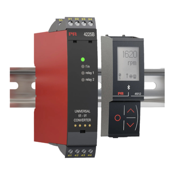
- Page 1 PERFORMANCE MADE SMARTER Product manual 4225 Universal f/I–f/f converter T E M P E R AT U R E I . S . I N T E R FA C E S CO M M U N I C AT I O N I N T E R FA C E S...
- Page 2 6 Product Pillars to meet your every need Individually outstanding, unrivalled in combination With our innovative, patented technologies, we make signal conditioning smarter and simpler. Our portfolio is composed of six product areas, where we offer a wide range of analog and digital devices covering over a thousand applications in industrial and factory automation.
-
Page 3: Table Of Contents
Universal f/I-f/f converter 4225 Table of contents Warning .................... -
Page 4: Warning
General mounting, connection and disconnection of wires. Troubleshooting the device. HAZARD- Repair of the device and replacement of circuit breakers must be done by PR electronics A/S only. VOLTAGE Warning Do not open the front plate of the device as this will cause damage to the connector for the PR 4500 communication interfaces. - Page 5 Should there be any doubt as to the correct handling of the device, please contact your local distributor or, alternatively, PR electronics A/S www.prelectronics.com Mounting and connection of the device should comply with national legislation for mounting of electric materials, i.e. wire cross section, protective fuse, and location.
-
Page 6: How To Demount System 4000
How to demount system 4000 Picture 1: The device is detached from the DIN rail by moving the bottom lock down. Mounting / demounting the PR 4500 communication interfaces 1: Insert the tabs of the PR 4500 into the slots at the top of the device. 2: Hinge the PR 4500 down until it snaps into place. -
Page 7: Functional Highlights
Universal f/I-f/f converter 4225 • Front-programmable • Input: NAMUR, NPN, PNP, Tacho, TTL & S0 • Output: Programmable bipolar mA / V, frequency or relay • Universal power supply 21.6…253 VAC / 19.2...300 VDC Functional highlights • Measures frequencies up to 100 kHz. -
Page 8: Applications
Applications Input signals: + Supply + Supply ∼ Special trig NAMUR Contact Tacho current & voltage (NPN) Output signals: 4225A 4225B 4225C Analog, 0/4...20 mA, Relays Analog, 0/4...20 mA, voltage and relay voltage and frequency Relay 2 (±) (±) (±) (±) 2-wire 2-wire... -
Page 9: Connections
Connections Supply 31 32 33 34 Inputs: Special current Special voltage Tacho 41 42 43 44 + supply 5...17 V + supply 5...17 V ∼ Contact (NPN) 41 42 + supply 5...17 V + supply 5...17 V + supply + supply NAMUR 41 42 + supply 8.3 V... - Page 10 Connections Outputs: 4225A Current 2-wire transmitter (Active output) (Passive output) Bu ered voltage Relay 21 22 23 24 (±) (±) 4225B Relays 4225C Current 2-wire transmitter Frequency (Active output) (Passive output) Bu ered voltage (Push / pull) 21 22 23 24 (±) (±) Frequency...
-
Page 11: Block Diagram
Block diagram 4225V100-UK... -
Page 12: Specifications
Specifications Order Type Output 4225 1 analog output and 1 relay 2 relays 1 analog output and 1 frequency output Accessories 4501 = Display / programming front 4511 = Modbus communication enabler 4512 = Bluetooth communication enabler Note: The PR 4500 communication interfaces are approved and certified as an add-on component to the 4000 series of devices. - Page 13 Accuracy, the greater of basic and absolute values: Input Type Basic accuracy Absolute accuracy Temperature coefficient Frequency input ≤ 0.0002 Hz ≤ ±0.01% of input frequency ≤ ±0.0005% / °C Output Type Basic accuracy Absolute accuracy Temperature coefficient Current output 8 µA ≤...
- Page 14 Auxiliary supplies Sensor supply limitation (terminal 44) ..... . . 20 mA, 5…17 V Input specifications Frequency input Frequency range ........0.001 Hz to 100 kHz Time range, time function .
- Page 15 Special voltage input User-programmable trig-levels......-0.05...6.50 V *Hysteresis, min........50 mV Input impedance, programmable: High Z .
- Page 16 Relay outputs Relay functions........Setpoint, Window, Sensor error, Latch, Power and Off Hysteresis .
- Page 17 **Power output limitations - 4225C Power limitations when using buffered voltage output (4225C only) 560 mW Overpower condition Correct operating range Digital output power Power limitations when using current output with 10 mA maximum output (4225C only) 460 mW Overpower condition Correct operating range...
- Page 18 Supported output configurations For the 4225A/-B a concurrent and independent operation of analog output and relay is possible. For 4225C the output is either presented on the analog or frequency output. In case of 4225C being configured for analog output, the frequency output can be configured for ‘relay mode’.
-
Page 19: Programming
The 4500 communication interfaces provide complete module programming and access to a wide range of operational features that help you when using the device. This chapter deals with the 4225 advanced features. The complete menu structure and programming options can be found in the Routing diagram section. - Page 20 Example – Input limits disabled ‘Min. selected ‘Max. selected Normal measuring range input’ - 15% input’ + 15% Extended measuring range 20.5 mA 20.0 mA 4.0 mA 3.8 mA Input: Output error indication = NONE Output limits and error indications – current output Input limit disabled NAMUR sensor error detection / input limit enabled Output error...
-
Page 21: Low Cut-Off Function
Output limits and error indications – custom frequency output, 50% duty cycle Input limit disabled NAMUR sensor error detection / input limit enabled Output error Output error Output limit Output limit Output limit Output limit Output span indication, indication, high high UP / DOWN NONE... -
Page 22: Square Root Function
Low cut-off function: As a part of the square root function of the 4225 it is possible to manually configure a low cut-off point. The feature is often used to suppress noise in the system. The low cut off point defines a point where the input/output relationship either changes to a linear relationship or the output is truncated to zero. - Page 23 Truncation to zero: 1.15 in_min 1.006 Fixed hysteresis: 0.5% of input 0.863 range 0.719 0.575 0.431 Input range Low cut-o point 0.288 0.144 Input range sqrt(x) Configuration Parameter Specification Condition 0.0 to 50.0% of Linear cut-off selected input range 0.0 to 50.0% of Independent of square root Low cut-off point selected input range...
-
Page 24: Relay Functions
Relay functions 6 different settings of relay function can be selected. Setpoint: The device works as a single limit switch. Window: The relay has a window that is defined by a low and high setpoint. On both sides of the window the relay has the same status. Error function: The relay is activated by sensor error. -
Page 25: Graphic Depiction Of Relay Action Window
Graphic depiction of relay action window Hysteresis (AIW) Setpoint Hysteresis (AOW) Window Window Hysteresis (AOW) Setpoint Hysteresis (AIW) OPEN CLOSED OPEN CLOSED OPEN A.I.W CLOSED OPEN CLOSED OPEN CLOSED CLOSED OPEN CLOSED OPEN CLOSED A.O.W OPEN CLOSED OPEN CLOSED OPEN Relay function: Active Inside Window / Active Outside Window = Normal function. -
Page 26: Advanced Settings Menu
If the configured password is not known, please contact PR electronics support - www.prelectronics.com/contact. Memory (MEM): In the memory menu you can save the configuration of the device in the PR 4500 communication interface, and then move the PR 4500 communication interface onto another device of the same type and download the configuration in the new device. - Page 27 Example setpoint function with latch Input signal ON delay OFF delay Setpoint (increasing) Hysteresis Time Closed Relay latched Relay contact (N.O.) Open Release not possible (setpoint still exceeded) Release not possible (setpoint-hysteresis still exceeded) Release not possible (OFF delay still exceeded) Release possible 4225V100-UK...
- Page 28 Fast setpoint adjustment and relay test 999.9 -199.9 1 Increase setpoint 2 Decrease setpoint 50.0 3 Save and exit the menu RELAY 1 1 and 2 simultaneously = relay test Power up Txt 72 999.9 -199.9 75.0 40.0 RELAY 2 Txt 72 10.4 mA ”Monitor”...
-
Page 29: Routing Diagram
Routing diagram If no key is activated for 1 minute, the display will return to the ”Monitor” menu without saving configuration changes. 1 Increase value / choose next parameter 2 Decrease value / choose previous parameter 3 Save the chosen value and proceed to the next menu Hold 3 Back to previous menu / return to ”Monitor”... - Page 30 -/+20 -/+10 S20-4 20-4 SETP NONE 20-0 WIND CURR S4-20 DISP 100.0 INCR PASS VOLT ZERO 4-20 PERC DECR ACTI FREQ DOWN 0-20 SETP CURR PERC SETP 50.0 DECR CURR ACTI 4-20 OUT.ERR REL.UNI R1.FUNC R1.CONT R1.SETP ACT.DIR OUT.TY OUT.MOD O.RANGE Txt 21 Txt 30...
- Page 31 HOLD CLOS 100.0 3600 3600 OPEN NONE NONE Relay 2 Similar to R1.HYST ERR.ACT ON.DEL OFF.DEL Relay 1 Txt 39 Txt 40 Txt 41 Txt 42 PSH.P PSH.P CONT.TY Txt 80 24.0 Continued on the next page PSH.P 24.0 HI.LVL Txt 81 Only shown if input type = NAMUR.
- Page 32 NONE HOLD HOLD CLOS CLOS 100.0k 115.0k ZERO OPEN OPEN 0.000 0.000 DOWN NONE NONE 0.00 NONE 0.00 NONE NONE ILIM.H ILIM.L LIM.LO ERR.ANA ERR.FRQ ERR.R2 ERR.R1 Txt 44 Txt 43 Txt 45 Txt 47 Txt 48 Txt 49 Txt 49 NONE HOLD HOLD...
-
Page 33: Routing Diagram, Advanced Settings (Adv.set)
Routing diagram, advanced settings (ADV.SET) MEM, DISP, CAL, SIM, SAVE PASS, LANG, LOAD IFUN, LATCH SAVE SETUP MEMORY Txt 52/1 Txt 53 O.VAL DISP O.VAL SETUP CONTRA LIGHT TAGNO_ LINE 3 Txt 52/2 Txt 54 Txt 55 Txt 56 Txt 57 100.0 100.0 “Monitor”... - Page 34 DE, DK, ES, FR, IT, SE, UK LANG SETUP LANGUA Txt 52/6 Txt 69 SQRT ZERO 0.000 0.000 L.COF 1.000 1.000 NONE NONE SQRT NONE IFUN NONE 0.000 1.000 ZERO SETUP I.FUNC SQRT.LO SQRT.HI CUT.TYP Txt 52/7 Txt 71 Txt 76 Txt 77 Txt 78 50.0...
-
Page 35: Routing Diagram, Manual Release Of Latched Relays
Routing diagram, manual release of latched relays Indication of a latched relay in monitor mode Rx.LATC = R1.LATC or R2.LATC or R1.LATC / R2.LATC alternating. 40.0 “Monitor” Rx.LATC ENT.SET Txt 73 Txt 74 To PASSW / ADV.SET 9999 0000 Correct ... -
Page 36: Help Text Overview
Help text overview Set correct password [21] Select output downscale at NAMUR sensor error Select output zero output at NAMUR sensor error Enter advanced setup menu? Select NAMUR sensor input Select output upscale at NAMUR sensor error Select no error action - output undefined - at NAMUR Select S0 sensor input Select PNP sensor input (or Contact to supply) sensor error... - Page 37 [49] Select no error action - undefined relay state - at limit error Open relay contact at limit error Close relay contact at limit error Hold relay status at limit error [50] Set output response time [seconds] Set output and relay power-on delay [seconds] [51] [52] Enter Relay Latch setup...
-
Page 38: Operation
AO.SU Analog output supply error Verify output configuration and output connection * RAM error RA.ER Internal RAM error Contact PR electronics * A/D converter error AD.ER Internal A/D converter error Contact PR electronics * Internal flash error IF.ER Internal flash error... - Page 39 All error indications in the display flash once per second. The help text explains the error. If the error is an input loop error, the display backlight flashes as well - this is acknowledged (stopped) by pushing the button. Error is acknowledged by either stepping through the basic setup, or by resetting the device power. Some types of errors can only be acknowledged by resetting the device power.
-
Page 40: Document History
Document history The following list provides notes concerning revisions of this document. Rev. ID Date Notes 2135 Initial release of the product. 4225V100-UK... - Page 41 We are near you, all over the world Our trusted red boxes are supported wherever you are All our devices are backed by expert service and a 5-year business with a global reach. This means that we are warranty. With each product you purchase, you receive always nearby and know your local markets well.
- Page 42 Benefit today from PERFORMANCE MADE SMARTER PR electronics is the leading technology company specialized in making industrial process control safer, more reliable and more efficient. Since 1974, we have been dedicated to perfecting our core competence of innovating high precision technology with low power consumption.
Need help?
Do you have a question about the 4225 and is the answer not in the manual?
Questions and answers