
Related Manuals for PR electronics 5225


Summary of Contents for PR electronics 5225
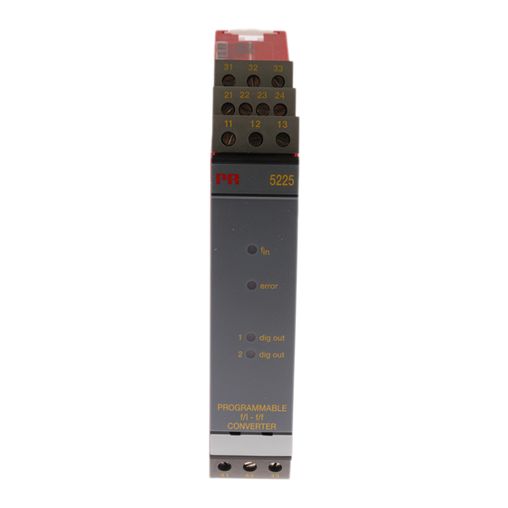
- Page 1 5 2 2 5 P r o g r a m m a b l e f / i - f / f c o n v e r t e r N o . 5 2 2 5 V 1 0 1 - U K F r o m s e r .
- Page 2 Vores motto »Signals the Best« er indbegrebet af denne filosofi – og din garanti for kvalitet. PR electronics A/S offers a wide range of analog and digital signal conditioning devices for industrial automation. The product range includes Isolators, Displays, Ex Interfaces, Temperature Transmitters, and Multifunctional Devices.
-
Page 3: Table Of Contents
In general ....................Applications....................Technical characteristics ..............Input ......................Analogue output ..................Digital output(s) ..................10 Relay outputs ................... 10 Status indication ..................10 Electrical specifications................ 11 Order ......................15 Block diagram ................... 15 5225 connection to Loop Link ............16 5225V101-UK... -
Page 4: Warning
General mounting, connection and disconnection of wires. Troubleshooting the device. Repair of the device and replacement of circuit breakers must be done by PR electronics A/S only. WARNING SYSTEM 5000 must be mounted on DIN rail according to DIN 46277. The communication connector of SYSTEM 5000 is... -
Page 5: Safety Instructions
Should there be any doubt as to the correct handling of the device, please contact your local distributor or, alternatively, PR electronics A/S www.prelectronics.com Mounting and connection of the device should comply with national legislation for mounting of electric materials, i.a. wire cross section, protective fuse, and location. - Page 6 When disconnected, the device may be cleaned with a cloth moistened with distilled water. LIABILITY To the extent the instructions in this manual are not strictly observed, the custom er cannot advance a demand against PR electronics A/S that would otherwise exist according to the concluded sales agreement. 5225V101-UK...
-
Page 7: How To Dismantle System 5000
HOW TO DISMANTLE SYSTEM 5000 First, remember to demount the connectors with hazardous voltages. By lifting the bottom lock, the device is detached from the DIN rail as shown in picture 1. Then, by lifting the upper lock and pulling the front plate simultaneously the PCB is removed as shown in picture 2. -
Page 8: In General
0...20000 Hz ---------------------------------------------------------------------------------------------------------------- IN GENERAL By way of a standard PC and the Loop Link programming kit, the 5225 f/I - f/f Converter is configured acc. to the requested function. Alternatively, the 5225 may be delivered fully-configured acc. to your specifications. -
Page 9: Applications
At contact input, the 50 Hz filter should be applied. The PRecon 5225 is protected against polarity reversal on input and supply. ANALOGUE OUTPUT The analogue current and voltage output can be scaled acc. to your choice in relation to the digital input. -
Page 10: Digital Output(S)
Active output is established by connecting the NPN to the PNP output (jumper pins 22-23). RELAY OUTPUTS The PRecon 5225 can be delivered with 2 relay outputs that are programmed individual ly. STATUS INDICATION The 5225 is equipped with 4 front LEDs. -
Page 11: Electrical Specifications
ELECTRICAL SPECIFICATIONS Specifications range: -20°C to +60°C Common specifications: Supply voltage ............19.2...28.8 VDC Internal consumption ..........1.7 W Max. consumption ............ 3.5 W Power-up delay (digital outputs) ...... 0...999 s Warm-up time ............30 s Communications interface ........Loop Link Signal / noise ratio .......... - Page 12 Input: General: Measurement range ..........0...20 kHz Min. measurement range ........0.001 Hz Max. offset ..............90% of selected max. frequency Low cut off ..............0.001 Hz Min. pulse width (without filter) ....... 25 µs Min. period (without filter)........50 µs Max.
- Page 13 TTL input: Trig-level LOW ............≤ 0.8 VDC Trig-level HIGH ..........≥ 2.0 VDC Input impedance ............≥ 100 kΩ S0 input acc. to DIN 43 864: Trig-level LOW ............≤ 2.2 mA Trig-level HIGH ............≥ 9.0 mA Input impedance ............800 Ω Analogue output: Current output: Signal range ...............
- Page 14 Relay output: Isolation, test / operation ........3.75 kVAC / 250 VAC Frequency max............20 Hz V max................250 VRMS I max................2 A / AC Max. AC power ............500 VA Max. load at 24 VDC ..........1 A Observed authority requirements: Standard: EMC 2004/108/EC ..........
-
Page 15: Order
ORDER Type Version Output 5225 Standard Analogue + NPN / PNP Analogue + relay output BLOCK DIAGRAM Front comm. Input gnd. Supply +24 VDC 5…17 VDC Supply gnd. 5…17V+ Vreg. Relay 2 Error Option Relay 2 / PNP Dig out 2 Sup. -
Page 16: 5225 Connection To Loop Link
5225 CONNECTION TO LOOP LINK Supply Loop Link Comm. 5225 5225V101-UK... - Page 17 Displays Programmable displays with a wide selection of inputs and outputs for display of temperature, volume and weight, etc. Feature linearization, scaling, and difference measurement functions for programming via PReset software. Ex interfaces Interfaces for analog and digital signals as well as HART signals between sensors / I/P converters / frequency signals and control systems in Ex zone 0, 1 &...
- Page 18 www.prelectronics.com sales-uk@prelectronics.com www.prelectronics.com sales-us@prelectronics.com www.prelectronics.cn sales-cn@prelectronics.com www.prelectronics.be sales-be@prelectronics.com Head office Denmark www.prelectronics.com PR electronics A/S sales-dk@prelectronics.com Lerbakken 10 tel. +45 86 37 26 77 DK-8410 Rønde fax +45 86 37 30 85...
Need help?
Do you have a question about the 5225 and is the answer not in the manual?
Questions and answers