
Related Manuals for PR electronics 2255


Summary of Contents for PR electronics 2255
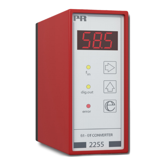
- Page 1 2 2 5 5 f / I - f / f c o n v e r t e r N o . 2 2 5 5 V 1 0 2 - U K F r o m s e r . n o . 9 8 0 4 3 1 0 0 1...
- Page 2 Vores motto »Signals the Best« er indbegrebet af denne filosofi – og din garanti for kvalitet. PR electronics A/S offers a wide range of analog and digital signal conditioning devices for industrial automation. The product range includes Isolators, Displays, Ex Interfaces, Temperature Transmitters, and Multifunctional Devices.
-
Page 3: Table Of Contents
- f/f CONVERTER TYPE 2255 CONTENTS Warning ....................... Symbol identification ................Safety instructions ................. How to dismantle system 2200 ............General ......................Technical characteristics ..............Input ......................Auxiliary supplies ................... Output(s) ....................Status indication ..................Electrical specifications................ Order ......................11 Analogue output programming by way of jumpers .... -
Page 4: Warning
General mounting, connection and disconnection of wires. Troubleshooting the device. Repair of the device and replacement of circuit breakers must be done by PR electronics A/S only. WARNING To keep the safety distances, devices with two built-in relays must not be connected to both hazardous and non-hazardous voltages on the same device’s relay contacts. -
Page 5: Symbol Identification
SYMBOL IDENTIFICATION Triangle with an exclamation mark: Warning / demand. Potentially lethal situations. The CE mark proves the compliance of the device with the requirements of the directives. The double insulation symbol shows that the device is protected by double or reinforced insulation. - Page 6 When disconnected, the device may be cleaned with a cloth moistened with distilled water. LIABILITY To the extent the instructions in this manual are not strictly observed, the custom- er cannot advance a demand against PR electronics A/S that would otherwise exist according to the concluded sales agreement. 2255V102-UK...
-
Page 7: How To Dismantle System 2200
HOW TO DISMANTLE SYSTEM 2200 The back panel of the device is detached from the housing by way of a screw-driver as shown in picture 1 On a device with knobs, these must be removed before the PCB can be taken out as shown in picture 2. -
Page 8: General
• Supply voltage 24 VDC General The 2255 f/I - f/f converter is configured to the reque sted function by means of a menu-driven dialogue with keys and display in the front. Typical signalling device may be pulse generators e.g. flow meters, tacho-generators or inductive sensors. -
Page 9: Output(S)
The relay output (option) with change-over contact. 300 VA, max. 150 VRMS, 2 A. Max. DC load at 24 VDC is 1 A. Status indication 2255 is equipped with 3 status indicators in the front. f in: Indicates active input (inactive by the NPN input). -
Page 10: Electrical Specifications
Electrical specifications Specifications range ..........-20°C to +60°C Common specifications: Supply voltage ............19.2...28.8 VDC Internal consumption ..........2.4 W Isolation, test / operation ........1400 VAC / 150 VAC Warm-up time ............1 min. Signal / noise ratio ..........Min. 60 dB Signal dynamics, output ........ -
Page 11: Analog Output
NAMUR input: Trig-level LOW ............≤ 1.2 mA Trig-level HIGH ............≥ 2.1 mA Input impedance ............1000 Ω Sensor error detection: Short-circuit ............... ≥ 7.0 mA Breakage ..............≤ 0.2 mA Response time ............≤ 400 ms Tacho input: Trig-level LOW ............ - Page 12 Voltage output through internal shunt: Signal range ............... 0...10 VDC Min. signal range ............250 mV Max. offset ..............50% of selec. max. value Load (min.) ..............500 kΩ NPN output: Max. current ............... 130 mA Max. voltage .............. 28 VDC f/f converter output: Signal range ...............
-
Page 13: Order
Order Type Version Output 2255 Programmable Analogue + NPN output Analogue + relay output Analogue output programming by way of jumpers Output range 0...10 mA (current only) 0...20 mA (current only) 0...10 mA / 0...0.5 V 0...20 mA / 0...1.0 V 0...10 mA / 0...5.0 V... -
Page 14: Block Diagram
BLOCK DIAGRAM 2255V102-UK... -
Page 15: Programming / Operating The Function Keys
PROGRAMMING / OPERATING THE FUNCTION KEYS DOCUMENTATION FOR ROUTING DIAGRAM GENERAL: The programming is menu-controlled. The main menus are numbered in level 0 (x.0), and the submenus are numbered in level 1 (x.1 to x.5). Each submenu has an accompanying entry menu. The menus are structured in such a way that the menus most frequently used are closer to the default menu 0.0. - Page 16 2255V102-UK...
- Page 17 2255V102-UK...
-
Page 18: Digital Output
SETTING OF f/I CONVERTER WITH ANALOGUE AND DIGITAL OUTPUT The following describes the routing diagram menu points from 0.0 to 5.5 for setting the f/I converter with analogue and digital output. EXAMPLE: Frequency span .........0...12550.5 Hz Analogue output .......4...20 mA Response time ........2.5 s Alarm frequencies ......<... - Page 19 2.0 InH - Setting of 100% frequency. 2.1 H-.- 100% setting of frequency in kHz. Entering of example = 012. Valid selections are 0...20.0 kHz. 2.2 -H.- 100% setting of frequency in Hz. Entering of example = 550. Valid selections are 0...999 Hz. 2.3 —.H 100% setting of frequency in mHz.
- Page 20 4.0 dOU - Digital setting of output 4.1 dLO - Setting of setpoint / limit frequency in % of the frequency span. This value corresponds to the setpoint, when menu 4.4 dOA = { InC or dEC }, and it corresponds to the low limit frequency of a setpoint window when menu 4.4 dOA = { UOn or UOF }.
- Page 21 5.0 APP - Application selection 5.1 FUn - Funktion selection. On a function change, the unit resets and the display returns to default, menu 0.0. Possible functions are: 001 = f/I converter 002 = f/f converter 003 = Frequency generator Entering of example = 001.
-
Page 22: Routing Diagram: F/F Converter For Pulse
2255V102-UK... - Page 23 2255V102-UK...
-
Page 24: Setting Of F/F Converter To Pulse Division / Multiplication
SETTING OF f/f CONVERTER TO PULSE DIVISION / MULTIPLICATION The following describes the routing diagram menu points from 0.0 to 5.4 for setting the f/f converter. When the function is selected for f/f converter, the analogue output is disabled so that it assumes the value 0 mA. EXAMPLE: Sensor ........NAMUR Output frequency ...Input frequency divided by 6.75... - Page 25 4.0 dOU - Output pulse length setting 4.1 PLS - Setting of output pulse length in ms. Entering of example = 500 Valid selections are 0.5...999 ms (max. 1000 Hz) 5.0 APP - Application selection. 5.1 FUn - Function selection. On a function change, the unit resets and the display returns to default, menu 0.0.
-
Page 26: Routing Diagram: Frequency Generator
2255V102-UK... - Page 27 2255V102-UK...
-
Page 28: Setting Of Frequency Generator
SETTING OF FREQUENCY GENERATOR The following describes the routing diagram menu points from 0.0 to 5.4 for setting as a frequency generator. When the function is selected as a frequency generator, the analogue output is disabled. EXAMPLE: Output frequency ..... 12550.5 Hz Fast change of frequency .. - Page 29 1.0 FOU - Output frequency setting 1.1 F-.- - Setting of output frequency in kHz. Entering of example = 012. Valid selections are 0...20.0 kHz. 1.2 -F.- - Setting of output frequency in Hz. Entering of example = 550. Valid selections are 0...999 Hz. 1.3 —.F - Setting of output frequency in mHz.
- Page 30 5.3 dSP - Default display units. Entering of example = E 3 Possible selections are E 3 display in kHz, E 0 display in Hz or E-3 display in mHz. 5.4 PAS - Password selection. When the password is 040, changes may be made in all menu points. When the password is <>...
- Page 31 Displays Programmable displays with a wide selection of inputs and outputs for display of temperature, volume and weight, etc. Feature linearization, scaling, and difference measurement functions for programming via PReset software. Ex interfaces Interfaces for analog and digital signals as well as HART signals between sensors / I/P converters / frequency ®...
- Page 32 www.prelectronics.com sales-uk@prelectronics.com www.prelectronics.com sales-us@prelectronics.com www.prelectronics.cn sales-cn@prelectronics.com www.prelectronics.be sales-be@prelectronics.com Head office Denmark www.prelectronics.com PR electronics A/S sales@prelectronics.dk Lerbakken 10 tel. +45 86 37 26 77 DK-8410 Rønde fax +45 86 37 30 85...
Need help?
Do you have a question about the 2255 and is the answer not in the manual?
Questions and answers