
Related Manuals for PR electronics 3114


Summary of Contents for PR electronics 3114
- Page 1 3 1 1 4 I s o l a t e d U n i v e r s a l C o n v e r t e r N o . 3 1 1 4 V 1 0 1 - U K...
- Page 2 PR electronics A/S tilbyder et bredt program af analoge og digitale signalbehandlingsmoduler til industriel automation. Programmet består af Isolatorer, Displays, Ex-barrierer, Temperaturtransmittere, Universaltransmittere mfl. Vi har modulerne, du kan stole på i selv barske miljøer med elektrisk støj, vibrationer og temperaturud- sving, og alle produkter opfylder de strengeste internationale stan- darder.
-
Page 3: Table Of Contents
IsolatED UnIvERsal ConvERtER 3114 ContEnts Warning ..................Safety instructions ................UL installation ................cFMus installation in Division 2 or Zone 2 ........ IECEx, ATEX installation in Zone 2 ..........Flexible supply ................Mounting and demounting of system 3000 ........Installation on DIN rail .............. -
Page 4: Warning
The connector behind the front cover of 3114 is connected to the input terminals on which dangerous voltages can occur. Potential electrostatic charging hazard. To avoid the risk of... - Page 5 symbol IDEntIFICatIon triangle with an exclamation mark: Read the manual before installation and commissioning of the device in order to avoid incidents that could lead to personal injury or mechanical damage. the CE mark proves the compliance of the device with the essential requirements of the directives.
-
Page 6: Safety Instructions
Should there be any doubt as to the correct handling of the device, please contact your local distributor or, alternatively, PR electronics a/s www.prelectronics.com Mounting and connection of the device should comply with national legislation for mounting of electric materials, i.e. wire cross section, protective fuse, and location. -
Page 7: Cfmus Installation In Division 2 Or Zone 2
The power supply unit must comply with NEC Class 2, as described by the National Electrical Code (ANSI / NFPA 70). ® cFmus InstallatIon In DIvIsIon 2 oR ZonE 2 Class I, Div. 2, Group A, B, C, D T4 or I, Zone 2, AEx nA IIC T4 or Ex nA IIC T4. In class I, Division 2 or Zone 2 installations, the subject equipment shall be mounted within a tool-secured enclosure which is capable of accepting one or more of Class I, Division 2 wiring methods specified in the National Electrical... - Page 8 To the extent the instructions in this manual are not strictly observed, the customer cannot advance a demand against PR electronics A/S that would otherwise exist according to the concluded sales agreement. 3 1 1 4 V 1 01 - UK...
-
Page 9: Flexible Supply
FlEXIblE sUPPly The units can be supplied with 24 The power connector unit 3405 is a VDC±30% via direct wiring and a loop standalone supply unit which supplies the power rail. With 3405, up to 100 between the devices. This permits the supply of up to 130 units. -
Page 10: Mounting And Demounting Of System 3000
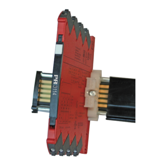
moUntIng anD DEmoUntIng oF systEm 3000 Picture 1: Mounting on DIN rail / power rail. Click the device onto the rail Picture 2: Demounting from DIN rail / power rail . First, remember to demount the connectors with hazardous voltages. Detach the device from the rail by lifting the bottom lock. -
Page 11: Installation On Din Rail
InstallatIon on DIn RaIl To avoid short circuit between the power rail connectors on the 3000 devices and the screws holding the 7.5 mm DIN rail, the head of the screws shall be no more than 3.5 mm high. 35 mm >... -
Page 12: Highlights
• When 3114 is used in combination with the 4501 display / programming front and ConfigMate 4590, all operational parameters can be modified to suit any application. As the 3114 is designed with electronic hardware switches, it is not necessary to open the device for setting of DIP-switches. • A green front LED indicates normal operation and malfunction. -
Page 13: Product Overview
Product overview PR type no. 3114 PR product name Isolated universal converter Universal DC / DC and temperature Description converter with loop supply output Parameterisation 4501 / ConfigMate 4590 RTD, TC and potentiometer 2-, 3-, and 4-wire Input signal 0...10 V 0...20 mA... -
Page 14: Pr 4501 Display / Programming Front
Functions and configuration options are described in the section ”Configuration /operating the function keys”. application • Communications interface for modification of operational parameters in 3114. • Can be moved from one 3114 device to another and download the configuration of the first device to subsequent devices. technical characteristics • LCD display with 4 lines; Line 1 (H=5.57 mm) shows input signal, line 2 (H=3.33... -
Page 15: Configmate 4590 Adapter
ConFIgmatE 4590 aDaPtER Connect the adapter by opening the front plate on 3114 and inserting the jack into the plug. 3114 4590 Once configuration of the device with 4501 has been terminated, the parameters can be transferred into the PC-based PReset program. The included USB cable... - Page 16 3114 = Isolated universal converter 4501 = Display / programming front 4590 = Configmate adapter Electrical specifications: Specifications range ........-25°C to +70°C Common specifications: Supply voltage, universal ......16.8...31.2 VDC Max. consumption........1.2 W Fuse ............. 400 mA SB / 250 VAC Isolation voltage, test / working ....
-
Page 17: Tc Type
basic values Input Basic Temperature type accuracy coefficient ≤ ±16 µA ≤ ±1.6 µA / °C ≤ ±0.8 mV ≤ ±0.08 mV / °C 0...1 V & 0.2...1 V 0...5 V, 1...5 V, ≤ ±0.8 mV / °C ≤ ±8 mV 0...10 V &... - Page 18 RtD, linear resistance and potentiometer input: Input Min. Max. type value value Standard Pt100 -200°C +850°C IEC60751 Ni100 -60°C +250°C DIN 43760 0 Ω 10000 Ω Lin. R 10 Ω Potentiometer 100 kΩ Input for RTD types: Pt10, Pt20, Pt50, Pt100, Pt200, Pt250, Pt300, Pt400, Pt500, Pt1000 Ni50, Ni100, Ni120, Ni1000 Cable resistance per wire (max.), RTD ..
-
Page 19: Voltage Output
Current input: Measurement range ........0...20 mA Programmable measurement ranges ..0...20 and 4...20 mA Input resistance ........... Nom. 20 Ω + PTC 50 Ω Sensor error detection: Loop break 4...20 mA......Yes voltage input: Measurement range ........0...12 VDC Programmable measurement ranges .. - Page 20 approvals Det Norske Veritas, Ships & Offshore ..Stand. f. Certification No. 2.4 Germanischer Lloyd ........V1-7-2 ATEX 94/9/EC ..........EN 60079-0, -15 IECEx ............IEC 60079-0, -15 cFMus ............FM 3600, 3611, 3810 CSA E60079-0, -15 CSA 22.2 -213 EMC 2004/108/EC ........
-
Page 21: Display Readout On The 4501 Of Sensor Error Detection And Input Signal Outside Range
Display readout on the 4501 of sensor error detection and input signal outside range Sensor error check: Device: Configuration Sensor error detection: OUT.ERR=NONE. 3114 Else: Outside range readout (IN.LO, IN.HI): If the valid range of the A/D converter or the polynomial is exceeded Input Range Readout Limit IN.LO... -
Page 22: Error Indications
No communication Error levels on Input error - check input connection and reset power IN.ER measurement inputs* Offline configuration mode (3114 powered by Programming mode only - no output signal PROG. communications interface)*** Configuration read from Invalid configuration type or version TY.ER... -
Page 23: Connections
ConnECtIons Input Output Supply 81 82 83 84 85 Input signals supply Current 1 Supply + Supply - Power rail connections Potentiometer Voltage Current 2 output signals Current Voltage 31 1 4 V 1 0 1 - UK... -
Page 24: Installation On Power Rail
InstallatIon on PoWER RaIl Module stop The 3114 can be installed on a power rail (PR part number 9400) supported, if necessary, by module stop for power rail (PR part number 9404). Power supply units can be mounted on the power rail according to customer requirements. -
Page 25: Marking
The front cover of the 3114 series has been designed with an area for affixation of a click-on marker. The area assigned to the marker measures Markers from Weidmüller’s MultiCard System, type MF 5/7.5, are suitable. 31 1 4 V 1 0 1 - UK... -
Page 26: Led Indication
lED InDICatIon The device is equipped with a green power LED in the front to indicate the operation status, see the table below. output and Condition action required loop supply No supply / Connect supply / device error or De-energized replace device code-flash CRC error 1 Flash... -
Page 27: Default Configuration
DEFaUlt ConFIgURatIon Input Input type ............ Temperature Voltage input ..........0...10 V Current input ..........4...20 mA Sensor connection (RTD+resistance) ..3 wire R input range ..........0...1000 Temperature unit ......... °C Temperature type ........Pt Pt type ............Pt100 Ni type ............ -
Page 28: Configuration / Operating The Function Keys
Documentation for routing diagram. In general When configuring the 3114, you will be guided through all parameters and you can choose the settings which fit the application. For each menu there is a scrolling help text which is automatically shown in line 3 on the display. - Page 29 signal and sensor error indication without display front Status of the unit can also be read from the green LED in the front of the device. Green flashing LED 13 Hz indicates normal operation. Green flashing LED 1 Hz indicates sensor error. No light in the LED indicates internal error.
- Page 30 selection of units After choosing the input signal type you can choose the process units which will be displayed in text line 2 (see table). By selection of temperature input the process value is always displayed in Celsius or Fahrenheit. This is selected in the menu point after selection of temperature input.
- Page 31 Power up Hold 1 and 2: Toggle Line 3 function between A.Out / TAG. (Setting is volatile - use DISP setup menu to change and store Line 3 function.) 40.0 10.4 2-10 VOLT 0-10 CURR 1111 LIN.R 111.1 0000 POTM 0.2-1 11.11 999.9...
-
Page 32: Routing Diagram
RoUtIng DIagRam If no key is activated for 1 minute, the display will return to the default state 1.0 without saving configuration changes. 1 Increase value / choose next parameter 2 Decrease value / choose previous parameter 3 Accept the chosen value and proceed to the next menu Hold 3 Back to previous menu / return to menu 1.0 without saving 20-4 20-0... -
Page 33: Routing Diagram, Advanced Settings (Adv.set)
RoUtIng DIagRam aDvanCED sEttIngs (aDv.sEt) 2.0 In the submenu simulation (SIM) you must DISP press 3 to return to the default state 1.0. PASS SAVE LANG LOAD SAVE SETUP MEMORY Txt 26 Txt 27 A.OUT DISP A.OUT SETUP CONTRA LIGHT TAGNO_ LINE 3 Txt 26... -
Page 34: Scrolling Help Text In Display Line 3
sCRollIng HElP tEXt In DIsPlay lInE 3 [01] Set correct password [22] Select no error action - output undefined at error [02] Enter advanced setup menu? Select downscale at error [03] Select temperature input Select upscale at error Select potentiometer input Select 0.0-1 V output range Select linear resistance input [23]... - Page 35 Displays Programmable displays with a wide selection of inputs and outputs for display of temperature, volume and weight, etc. Feature linearisation, scaling, and difference measurement functions for programming via PReset software. Ex interfaces Interfaces for analogue and digital signals as well as HART signals between ®...
- Page 36 www.prelectronics.it sales@prelectronics.it www.prelectronics.se sales@prelectronics.se www.prelectronics.com sales@prelectronics.com www.prelectronics.com sales@prelectronics.com Head office Denmark www.prelectronics.com PR electronics A/S sales@prelectronics.dk Lerbakken 10 tel. +45 86 37 26 77 DK-8410 Rønde fax +45 86 37 30 85...
Need help?
Do you have a question about the 3114 and is the answer not in the manual?
Questions and answers