Table of Contents
Advertisement
Quick Links
Product manual
3114
Isolated universal converter
ZONE 2
Zone 2
T E M P E R AT U R E
|
I . S . I N T E R FA C E S
No. 3114V105- UK
From serial no. : 211696 077
ZONE 2 / DIV 2
|
CO M M U N I C AT I O N I N T E R FA C E S
|
M U LT I F U N C T I O N A L
|
I S O L AT I O N
PERFORMANCE
MADE
SMARTER
|
D I S P L AY
Advertisement
Table of Contents

Related Manuals for PR electronics 3114


Summary of Contents for PR electronics 3114
- Page 1 PERFORMANCE MADE SMARTER Product manual 3114 Isolated universal converter ZONE 2 Zone 2 ZONE 2 / DIV 2 T E M P E R AT U R E I . S . I N T E R FA C E S...
- Page 2 6 Product Pillars to meet your every need Individually outstanding, unrivalled in combination With our innovative, patented technologies, we make signal conditioning smarter and simpler. Our portfolio is composed of six product areas, where we offer a wide range of analog and digital devices covering over a thousand applications in industrial and factory automation.
-
Page 3: Table Of Contents
Isolated universal converter 3114 Table of contents Warnings .................... -
Page 4: Warnings
HAZARDOUS VOLTAGE The connector behind the front cover of 3114 is connected to the input terminals on which dangerous voltages can occur. Potential electrostatic charging hazard. To avoid the risk of explosion due to electrostatic charging of the enclosure, do not handle the units unless the area is known to be safe, or appropriate safety measures are taken to avoid electrostatic discharge. -
Page 5: Safety Instructions
Should there be any doubt as to the correct handling of the device, please contact your local distributor or, alternatively, PR electronics A/S www.prelectronics.com Mounting and connection of the device should comply with national legislation for mounting of electric materials, e.g. wire cross section, protective fuse, and location. -
Page 6: Mounting / Demounting Of System 3000
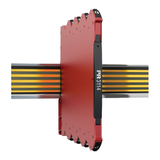
PR 3114 can be mounted on DIN rail or power rail. When installing a PR 3114 device with power rail connectors on a standard 7.5 mm DIN rail the head of the screws holding the rail shall be no more than 3.5 mm high to prevent potential short circuit of the power rail connectors. -
Page 7: Installation On Din Rail / Power Rail
Marking The front cover of the PR 3114 has been designed with an area for affixation of a click-on marker. The area assigned to the marker measures 5 x 7.5 mm. Markers from Weidmüller’s MultiCard System, type MF 5/7.5, are suitable. -
Page 8: Flexible Supply
Note: PR 3114-N can only be supplied via the DIN rail solution with direct wiring on each device. External fuse characteristics: The 2.5 A fuse must break after not more than 120 seconds at 6.4 A. -
Page 9: Applications
Programming • Configuration, monitoring, and diagnostics using PR 4500 detachable communication interfaces via the PR 4590 ConfigMate. As the 3114 is designed with electronic hardware switches, it is not necessary to open the device for setting of DIP-switches. • All programming can be password protected. -
Page 10: Connections
No connection Rail, supply + Input signals Rail, supply - Current 1 No connection No connection Potentiometer Voltage Current 2 Output signals Current Voltage Supply Supply + Supply - Power rail connections (Only type 3114 with power rail option) 3114V105-UK... -
Page 11: Specifications
3114 Isolated universal converter With power rail connector / terminals Supplied via terminals : -N Example: 3114-N (Isolated universal converter, supplied via terminals) Accessories 4510 = Display / programming front 4511 = Modbus communication enabler* 4590 = ConfigMate 9404 = Module stop for rail *Note: The PR 4511 communication interface with serial number >... - Page 12 Fuse ......... . . 400 mA SB / 250 VAC Isolation voltage, test .
- Page 13 RTD, linear resistance and potentiometer input: Input type Min. value Max. value Standard Pt100 -200°C +850°C IEC 60751 Ni100 -60°C +250°C DIN 43760 Linear resist. 0 Ω 10000 Ω Potentiometer 10 Ω 100 kΩ Input for RTD types: Pt10, Pt20, Pt50, Pt100, Pt200, Pt250, Pt300, Pt400, Pt500, Pt1000 Ni50, Ni100, Ni120, Ni1000 Cable resistance per wire (max.), RTD .
- Page 14 Current output: Signal range (span) ........0...23 mA Programmable signal ranges .
-
Page 15: Programming
Programming Default configuration Input Input type ........Temperature Voltage input . -
Page 16: Pr 4590 Configmate Programming
PR 4590 ConfigMate programming Connect the adapter by opening the front plate on PR 3114 and inserting the jack into the plug. A reference for the complete menu structure and programming options can be found in the section ‘Routing diagram’ on page 21. -
Page 17: Display Readout On The Pr 4500 Of Sensor Error Detection And Input Signal Outside Range
Display readout on the PR 4500 of sensor error detection and input signal outside range Sensor error check: Device: Configuration Sensor error detection: OUT.ERR=NONE. 3114 Else: Outside range readout (IN.LO, IN.HI): If the valid range of the A/D converter or the polynomal is exceeded Input Range Readout Limit IN.LO... -
Page 18: Error Indications
No communication Input error - check input connection and reset IN.ER Error levels on measurement inputs* power Offline configuration mode (3114 powered by Programming mode only - no output signal PROG. communications interface)*** Configuration read from EEprom has invalid type Invalid configuration type or version TY.ER... -
Page 19: Advanced Settings Menu
If the configured password is not known, please contact PR electronics support - www.prelectronics.com/contact. Memory (MEM): In the memory menu you can save the configuration of the device in the PR 4500 communication interface, and then move the PR 4500 communication interface onto another device of the same type and download the configuration in the new device. - Page 20 Hold 1 and 2: Power up Toggle Line 3 function between A.Out / TAG. (Setting is volatile - use DISP setup menu to change and store Line 3 function.) 40.00 2-10 VOLT 0-10 CURR 1111 10.4 LIN.R 111.1 0000 POTM 0.2-1 11.11 *1.0...
-
Page 21: Routing Diagram
Routing diagram If no key is activated for 1 minute, the display will return to the default state 1.0 without saving configuration changes. 1 Increase value / choose next parameter 2 Decrease value / choose previous parameter 3 Save the chosen value and proceed to the next menu Hold 3 Back to previous menu / return to menu 1.0 without saving. -
Page 22: Routing Diagram, Advanced Settings (Adv.set)
Routing diagram, advanced settings (ADV.SET) MEM, DISP, SAVE CAL, SIM, LOAD PASS, LANG SAVE SETUP MEMORY Txt 26 Txt 27 A.OUT DISP A.OUT SETUP CONTRA LINE 3 LIGHT TAGNO_ Txt 26 Txt 28 Txt 31 Txt 29 Txt 30 850.0 850.0 -200.0 -200.0... -
Page 23: Help Text Overview
Help text overview [01] Set correct password [19] Select 0-20 mA output range [02] Enter advanced setup menu? Select 4-20 mA output range [03] Select temperature input Select 20-0 mA output range Select 20-4 mA output range Select potentiometer input [22] Select no error action - output undefined at error Select linear resistance input... -
Page 24: Operation & Troubleshooting
Operation & troubleshooting The 3000 series devices provide multiple features for easy user operation and for performing efficient troubleshooting. Monitoring the operational status is easy from the front LED. Status indicator front LED Power - Green Output and Condition Action required loop supply No supply / device error or Connect supply /... -
Page 25: Installation Instructions
Installation instructions UL installation Use 60/75°C copper conductors only. Wire size ........AWG 26-12 UL file number . -
Page 26: Document History
Document history The following list provides notes concerning revisions of this document. Rev. ID Date Notes 1741 Model 3114-N added. Specifications for max. required power and power dissipation added. PESO/CCOE approval added. 2037 PESO/CCOE approval discontinued. 2108 CCC approval added. - Page 27 We are near you, all over the world Our trusted red boxes are supported wherever you are All our devices are backed by expert service and a 5-year business with a global reach. This means that we are warranty. With each product you purchase, you receive always nearby and know your local markets well.
- Page 28 Benefit today from PERFORMANCE MADE SMARTER PR electronics is the leading technology company specialized in making industrial process control safer, more reliable and more efficient. Since 1974, we have been dedicated to perfecting our core competence of innovating high precision technology with low power consumption.
Need help?
Do you have a question about the 3114 and is the answer not in the manual?
Questions and answers