Table of Contents

Related Manuals for PR electronics 3000 Series


Summary of Contents for PR electronics 3000 Series
- Page 1 3 0 0 0 s e r i e s 6 m m S e r i e s o f Te m p e r a t u r e C o n v e r t e r s M o d e l s n o .
- Page 2 PR electronics A/S tilbyder et bredt program af analoge og digitale signalbehandlingsmoduler til industriel automation. Programmet består af Isolatorer, Displays, Ex-barrierer, Temperaturtransmittere, Universaltransmittere mfl. Vi har modulerne, du kan stole på i selv barske miljøer med elektrisk støj, vibrationer og temperaturudsving, og alle produkter opfylder de strengeste internationale standarder.
-
Page 3: Table Of Contents
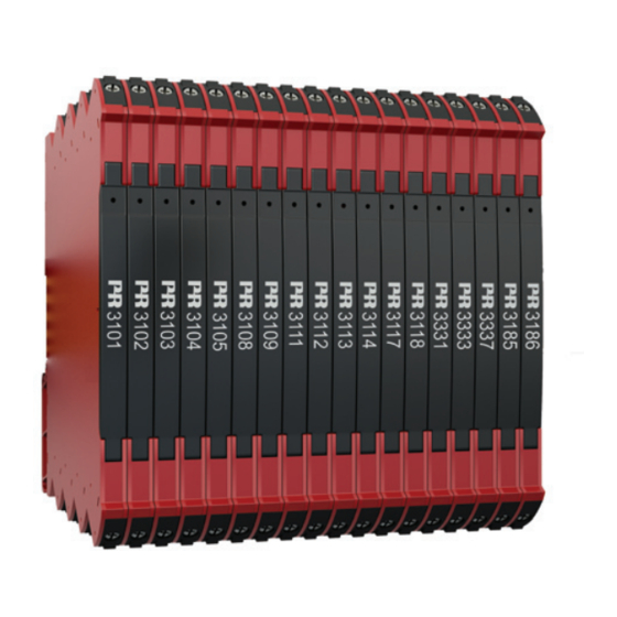
6 mm SERiES oF TEmPERATURE CoNVERTERS 3101 - 3102 - 3111 - 3112 - 3113 - 3331 - 3333 - 3337 CoNTENTS Warning ........................Safety instructions ....................Mounting on DIN rail ..................... Installation on DIN rail ..................Module stop ......................Flexible supply ...................... -
Page 4: Warning
Until the device is fixed, do not connect hazardous voltages to the device. Repair of the device must be done by PR electronics A/S only. In applications where hazardous voltage is connected to in-/ outputs of the device, sufficient spacing or isolation from wires, terminals and enclosure - to surroundings (incl. -
Page 5: Safety Instructions
SAFETy iNSTRUCTioNS RECEiPT AND UNPACKiNg Unpack the device without damaging it. The packing should always follow the device until this has been permanently mounted. Check at the receipt of the device whether the type corresponds to the one ordered. ENViRoNmENT Avoid direct sunlight, dust, high temperatures, mechanical vibrations and shock, as well as rain and heavy moisture. - Page 6 The 3000 System Isolators and Converters must be connected to limited output ® NEC Class 2 circuits, as outlined in the National Electrical Code (ANSI / NFPA 70), only. If the devices are connected to a redundant power supply (two separate power supplies), both must meet this requirement.
- Page 7 To prevent ignition of the explosive atmospheres, disconnect power before servicing and do not separate connectors when energised and an explosive gas mixture is present. Do not mount or remove devices from the power rail when an explosive gas mixture is present.
-
Page 8: Mounting On Din Rail
moUNTiNg oN DiN RAil The system 3000 devices can easily be mounted on a standard 35 mm DIN rail. Remove the system 3000 units from the rail by lifting the DIN rail mounting clip. Wire size AWG 26-12 / 0.13 x 2.5 mm stranded wire. -
Page 9: Installation On Din Rail
iNSTAllATioN oN DiN RAil To avoid short circuit between the power rail connectors on the 3111, 3112 and 3113 devices and the screws holding the 7.5 mm DIN rail, the head of the screws shall be no more than 3.5 mm high. 35 mm >... -
Page 10: Flexible Supply
FlExiblE SUPPly Device daisy chain: Power rail solution #1: The 3101, 3102, 3111, 3112 and The 9410 power control unit can energize and power 96 W to the rail 3113 devices are powered by 24 VDC +/- 30%. External protective meaning that up to 137 pcs of 3111, fuse requirement:... -
Page 11: Marking
The hinged cover of the 3000 series has a space designed to accept a snap-on marker, which can be used to identify individual units. This space measures 5 x 7.5mm, and markers from Weidmuller’s MultiCard System, type MF 5/7.5, are suitable. -
Page 12: Applications
TEmPERATURE CoNVERTERS • Converts process measurements from Pt100, TC J and K temperature sensors to voltage or current outputs • Multiple pre-calibrated temperature ranges are selectable via DIP- switches • High accuracy, better than 0.05% and excellent 50/60 Hz noise suppression •... -
Page 13: Mounting / Installation
mounting / installation • Selectable DIP-mode for easy configuration of more than 1000 factory calibrated measurement ranges with HART® read only feature. • The narrow 6 mm housing and very low power consumption allows up to 165 units to be mounted per meter of DIN rail, without any air gap between units. • Wide temperature operation range of -25...+70°C. 3 00 0 V 1 01 - UK... -
Page 14: Order Codes
order codes: input output Pt100 Current isola- Supply HART® Volt- int. Ext. 2-, 3-, J & K Active Passive 4-wire 3101 24 VDC 3102 24 VDC 24 VDC / 3111 2.5 kV ... -
Page 15: Specifications
Specifications Environmental conditions: Specifications range ..........-25°C to +70°C Storage temperature ..........-40°C to +85°C Calibration temperature ........20...28°C Relative humidity............. < 95% RH (non-cond.) Protection degree ............ IP20 / EN60529 Installation ..............Pollution degree 2 and overvoltage category II mechanical specifications: Dimensions (HxWxD) .......... - Page 16 Response time HART® HART® Selectable read only mode mode < 30 ms < 300 ms < 60 ms 0.06...60 s 3101 3102 3111 3112 3113 3331 3333 ...
- Page 17 input specifications: Specifications for Pt100 input: Temperature range, Pt100 ........-200...+850°C - IEC 60751 Sensor current ............< 150 mA Sensor cable resistance ........< 50 W per wire Effect of sensor cable resistance, 3- / 4-wire ..< 0.002 Ω / Ω Sensor error detection ...........
- Page 18 Selectable voltage output low range High range min. Sensor Sensor load Range limit Range limit error error 3101 0/1...5 V 0/0.875...5.125 V 0/5.5 V 0/2...10 V 0/1.75...10.25 V 0/11 V 10 kW 3102 0/1...5 V 0/0.875...5.125 V 0/5.5 V 0/2...10 V 0/1.75...10.25 V 0/11 V 10 kW 3111 0/1...5 V 0/0.875...5.125 V 0/5.5 V 0/2...10 V...
-
Page 19: Dip-Switch Configuration
DiP-SWiTCH CoNFigURATioN 3101 and 3111 - TC J & K 3102 and 3112 - Pt100 *3101 - only int CJC 3331 - Pt100 & TC J/K 3333 - Pt100 3113 and 3337 - Pt100 & TC J/K + HART (Power must be cycled after DIP-switch positions are changed). 3 00 0 V 1 01 - UK... -
Page 20: Temperature Range Programming
TEmPERATURE RANgE PRogRAmmiNg Please note: 3101 and 3111 - only TC input available Valid TC J range: -100...+1200°C = correct DIP-switch setting Valid TC K range: -180...+1372°C = correct DIP-switch setting 3102, 3112 and 3333 - only Pt100 input available Valid Pt100 range: -200...+850 °C = correct DIP-switch setting ”Start temp”... -
Page 21: Front Led Indications
FRoNT lED iNDiCATioNS FoR 3101, 3102, 3111, 3112 AND 3113 lED (green) Condition output Action required Power-up 1 flash 0.5 s ON and OFF De-energized or Restart Flashing 13 Hz / 15 ms ON Device OK Energized Sensor error Flashing 1 Hz / 15 ms ON Up- or Downscale Check sensor indication Incorrect DIP-switch Correct setting Flashing 1 Hz / 500 ms ON... -
Page 22: Block Diagram And Wiring
bloCK DiAgRAm AND WiRiNg Input wiring External CJC (2- or 3-wire Pt100) Type *3101 - only 3101 internal CJC 1,2 & 3,4 1,2 & 3 2 & 3 3102 3111 1,2 & 3,4 1,2 & 3 2 & 3 3112 1,2 &... - Page 23 Displays Programmable displays with a wide selection of inputs and outputs for display of temperature, volume and weight, etc. Feature linearization, scaling, and difference measurement functions for programming via PReset software. Ex interfaces Interfaces for analog and digital signals as well as HART signals between sensors / I/P converters / ®...
- Page 24 www.prelectronics.se sales-se@prelectronics.com www.prelectronics.co.uk sales-uk@prelectronics.com www.prelectronics.com sales-us@prelectronics.com www.prelectronics.cn sales-cn@prelectronics.com Head office Denmark www.prelectronics.com PR electronics A/S sales-dk@prelectronics.com Lerbakken 10 tel. +45 86 37 26 77 DK-8410 Rønde fax +45 86 37 30 85...
Need help?
Do you have a question about the 3000 Series and is the answer not in the manual?
Questions and answers