Table of Contents
Advertisement
Quick Links
PROPER USE GUIDELINES
Cumulative Trauma Disorders can result from the prolonged use of manually powered hand tools. Hand tools are intended for occasional use and low volume
applications. A wide selection of powered application equipment for extended- - use, production operations is available.
Nut
Die Set 2063956- - 2
Wire Crimper
(Upper Die)
Lower
Contact
Support
Nut
Anvil (Lower)
Wire Die
DIE ASSEMBLY
DIE ASSEMBLY
PART NUMBER
2063956--2
2063956 2
1. INTRODUCTION
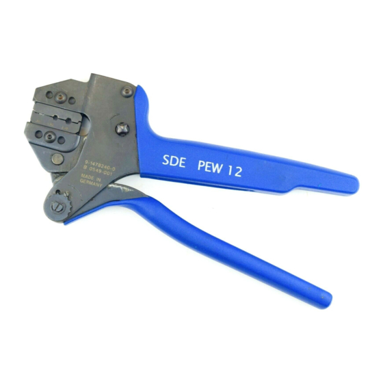
SDE PEW--12 Hand Tool Assembly 2063956--1
consists of SDE PEW--12 Frame Assembly
9--1478240--0 and die set assembly 2063956--2. See
Figure 1. The tool is used to crimp Slim Seal SSL
Contacts.
Dimensions in this instruction sheet are in
NOTE
millimeters [with inches in brackets]. Figures and
i
illustrations are for reference only and are not
drawn to scale.
Reason for revision is given in Section 10, REVISION
SUMMARY.
E2010 Tyco Electronics Corporation, Berwyn, PA
All Rights Reserved
TE logo and Tyco Electronics are trademarks.
*Trademark. Other product names, logos, or company names might be trademarks of their respective owners.
SDE PEW- 12 Hand Tool
Assembly 2063956- 1 with
Die Assembly 2063956- 2
Locator
Stationary
Jaw
Moving
Jaw
Insulation
Crimper
(Upper Die)
Anvil (Lower)
Insulation Die
CONTACT
CONTACT
(Pin)
2--2106124--7, 2--2106124--8,
2--2106124--9, 3--2106124--0
(Socket)
1--2106123--2, 1--2106123--4
TOOLING ASSISTANCE CENTER 1- - 800- - 722- - 1111
PRODUCT INFORMATION 1- - 800- - 522- - 6752
Ratchet
Adjustment
Wheel
SIZE
INSULATION DIA
2
0.20--0.33 mm
1.40--2.10
[24--22 AWG]
[24 22 AWG]
[ 055 083]
[.055--.083]
Figure 1
2. DESCRIPTION
The tool frame features two jaws, a handle, ratchet
adjustment wheel, and an emergency ratchet release.
The die set consists of an indenter (upper die) and an
anvil (lower die). The tool frame holds a die assembly
with two crimping chambers. See Figure 1. Die
retaining pins and die retaining screws are used to
position and secure the dies in the tool frame.
The tool features a ratchet and an adjustment wheel
with a range of settings. The ratchet ensures that the
tool has completed the cycle and will not release until
the handles have been FULLY closed, unless the
emergency ratchet release is rotated to manually
release the ratchet. The adjustment wheel controls
the amount of handle pressure exerted on the dies
during the crimping procedure.
This controlled document is subject to change.
For latest revision and Regional Customer Service,
visit our website at www.tycoelectronics.com
Instruction Sheet
408- - 10370
07 OCT 10 Rev B
Handle
Emergency Ratchet
Release
Die Retention
Screws
Short Retaining
Pins (2)
Required
Long Retaining
Pins (2)
Required
WIRE
STRIP LENGTH
3.2--3.7
[ 126 146]
[.126--.146]
1 of 5
LOC B
Advertisement
Table of Contents

Related Manuals for Tyco Electronics 2063956-1


Summary of Contents for Tyco Electronics 2063956-1
- Page 1 PRODUCT INFORMATION 1- - 800- - 522- - 6752 For latest revision and Regional Customer Service, visit our website at www.tycoelectronics.com TE logo and Tyco Electronics are trademarks. LOC B *Trademark. Other product names, logos, or company names might be trademarks of their respective owners.
- Page 2 Refer to crimpers out of the tool jaws. Figure 2 and proceed as follows: 2 of 5 Rev B Tyco Electronics Corporation...
- Page 3 CAUTION 1. Refer to Figure 1 and select a wire (maximum damaged contact is evident, it should be size) for each crimp section listed. replaced. Contacts must not be re- - terminated. Rev B 3 of 5 Tyco Electronics Corporation...
- Page 4 9. REPLACEMENT Order replacements through your representative, or call 1--800--526--5142, or send a facsimile of your purchase order to 717--986--7605, or write to: CUSTOMER SERVICE (038--035) TYCO ELECTRONICS CORPORATION P.O. BOX 3608 Adjustment HARRISBURG, PA 17105--3608 Screw Ratchet Adjustment Wheel 10.
- Page 5 (Customer Manual 409- 10052) (Instruction Sheet 408- 4070) Battery Tool (Pin Die) 1213890- 1, - 2 Battery Tool (Shouldered Die) 1725837- 1, - 2 (Customer Manual 409- 10065) (Customer Manual 409- 10053) Rev B 5 of 5 Tyco Electronics Corporation...
- Page 6 X-ON Electronics Largest Supplier of Electrical and Electronic Components Click to view similar products for category: Punches & Dies Click to view products by manufacturer: TE Connectivity Other Similar products are found below : 58510-1 63454-1601 63457-0056 63457-3401 730-5/8 730BB-1-3/8 PV-670508-001 1328 1338 13782656 13782673 13782686 AR-24 1528-TL 1583609-1 1720 1762951-1 2063500-2 19031-0168 AR-20 CD5-8 313336-3 11-19-3122 539663-1 63446-2241 TL-18 0634451912 1762674-1 63454-0123 68240-1 68247-1 734252 313183-1 PA2029 119174-001 23846-1 11-40-5342 68010-2 690370015 730BB-1-1/8 730BB-1-1/16 19032-0048 63465-0023 11-40-4438 63457-0041 2906252-01 19032-0202 11-11-0054 11-11-0052 19813-...
Need help?
Do you have a question about the 2063956-1 and is the answer not in the manual?
Questions and answers