Burkert AirLINE 8644 Quick Start Manual
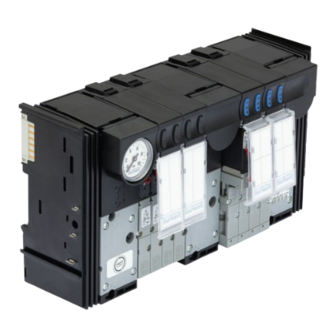
Modular valve island for pneumatics
Hide thumbs
Also See for AirLINE 8644:
- Operating instructions manual (224 pages) ,
- Quick start manual (58 pages) ,
- Operating instructions manual (70 pages)

Subscribe to Our Youtube Channel
Related Manuals for Burkert AirLINE 8644


Summary of Contents for Burkert AirLINE 8644
- Page 1 Type 8644 AirLINE Modular valve island for pneumatics Modulare Ventilinsel für Pneumatik Îlot de distributeurs modulaires pour la pneumatique Quickstart English Deutsch Français...
- Page 2 We reserve the right to make technical changes without notice. Technische Änderungen vorbehalten. Sous réserve de modifications techniques. © Bürkert Werke GmbH & Co. KG, 2011 - 2023 Operating Instructions 2307/02_EU-ML_00809514 / Original DE...
-
Page 3: Table Of Contents
Type 8644 Contents THE QUICKSTART ..............4 REMOVING THE VALVE BLOCK FROM THE STANDARD RAIL ..............13 1.1 Definition of terms ............4 Symbols used .............. 4 INSTALLATION OF THE VALVE ISLAND IN THE CONTROL CABINET ............14 INTENDED USE ..............5 Safety instructions ............. -
Page 4: The Quickstart
▶ Failure to observe these instructions may result in moderate or minor injuries. Operating instructions and data sheets for Bürkert products can be found on the Internet at: NOTE! country.burkert.com Warns of damage. Definition of terms Important tips and recommendations. Term... -
Page 5: Intended Use
Type 8644 Intended use INTENDED USE BASIC SAFETY INSTRUCTIONS These safety instructions do not take account of any The valve island Type 8644 has been designed to control pneumatic consumers in automation systems. The valve • contingencies or events which may occur during installation, island must only be used for controlling suitable pneumatic operation and maintenance of the devices;... - Page 6 Type 8644 Basic safety instructions ▶ Installation and maintenance work may only be carried out Risk of injury due to improper installation and maintenance. by authorised specialist personnel using suitable tools. ▶ Only allow trained technicians to perform installation and maintenance work.
-
Page 7: Notes On Compatibility And Revision Levels
Type 8644 Notes on compatibility and revision levels NOTES ON COMPATIBILITY AND REVISION LEVELS The valve island Type 8644 is available in combination with decentralised peripheral devices from the cooperation partners “WAGO”, “Phoenix Contact”, “Siemens” and “Rockwell Automation”. The “WAGO” variant was revised (see Chapter 4.1). The variants “Phoenix Contact”, “Siemens”... -
Page 8: Notes On Valve Islands Revision 2 (Only Applies To "Wago" Valve Islands)
Type 8644 Notes on compatibility and revision levels Valve island width per station 16 mm* REV.1 REV.2 Electronic modules REV.1 Pneumatic base modules REV.1 Pneumatic base modules REV.2 Connection modules REV.1 Connection modules REV.2 Solenoid valve Types 6526, 6527 and 0461 •... -
Page 9: Distinguishing Features Between Valve Islands Rev.1 And Rev.2
Type 8644 Notes on compatibility and revision levels Distinguishing features between valve Distinguishing features between islands REV.1 and REV.2 individual valves REV.1 and REV.2 Only applies to the “WAGO” variant valve islands. Only applies to the “WAGO” variant valve islands. Single valves REV.1: Colour of release rings (push-in connectors) The single valves Type 6524 3/2-way and Type 6525 5/2-way... -
Page 10: General Information
Tel. +49 (0) 7940 - 10 91 111 the EU Declaration of Conformity/UK Declaration of Conformity. Fax +49 (0) 7940 - 10 91 448 General technical data Email: info@burkert.com NOTE! International To avoid damage to the device, use only direct current to The contact addresses can be found on the back pages of the power the device. - Page 11 Type 8644 Technical data 6.2.1 Valve island type label when using the pilot valve Types 6524, 6525, 6526, 6527 0460, 0461 Device type Pressure range Vac. to 10 bar Revision marking UL devices: Vac. to 8 bar Serial number Operating voltage* 24 V DC Order number Voltage tolerance...
-
Page 12: Connect Valves
Type 8644 Connect valves CONNECT VALVES 6.2.3 Valve type label Single valves width per station 11 mm Device type Circuit function Type 6524 Type 6525 permitted pressure range 6524 C Operating voltage Make the pressure (± 10%), power 2,5—10bar supply as large-volume 24VBA0,8W as possible! W1XAW... -
Page 13: Single Valves Width Per Station 16 Mm
Type 8644 Removing the valve block from the standard rail Single valves width per station 16 mm REMOVING THE VALVE BLOCK FROM THE STANDARD RAIL Type 6526 Type 6527 DANGER! Make the pressure Danger due to electrical voltage! supply as large- ▶... -
Page 14: Installation Of The Valve Island In The Control Cabinet
Type 8644 Installation of the valve island in the control cabinet INSTALLATION OF THE VALVE There must be sufficient space between the valve block ISLAND IN THE CONTROL CABINET and the predecessor module (> 6 mm). → Detach modules/clips from the standard rail according to the Safety instructions manufacturer’s description. -
Page 15: Installation On Standard Rail
Type 8644 Installation of the valve island in the control cabinet CAUTION! NOTE! Valve island Type 8644 is supplied as a fully assembled device. Medium leakage and malfunction. Modifications may only be made by Bürkert. If seals are not properly positioned, leaks and functional impair- The valves are excluded from this and may be exchanged by ments may arise due to pressure loss. -
Page 16: Installation With Airline Quick
Type 8644 Installation of the valve island in the control cabinet Recommended distance when installing in the control cabinet: Valve island 30 mm 30 mm Type 8644 30 mm 60 mm AirLINE Quick Adapter Installation with AirLINE Quick For installation with AirLINE Quick, a cut-out must first be pro- vided in the control cabinet base or wall. This can be done, for example, with a laser or punch. - Page 17 Type 8644 Installation of the valve island in the control cabinet 9.3.1 Dimensions of the flange patterns for AirLINE Quick Control cabinet inner wall t >= 1.5 Ø 5.3 ± 0.2 R 6.5 only with O= 6 and O = 10 (O = number of holes) Space requirement for external reinforcing frame Figure 13: Flange pattern AirLINE Quick –...
-
Page 18: Installation
Type 8644 Installation INSTALLATION Variant 8-valve 12-valve 16-valve 10.1 Fluidic installation Special – – – feature DANGER! ± 0.4 ± 0.4 ± 0.4 Risk of injury from high pressure in the system. ± 0.3 ± 0.3 ± 0.4 ▶ Before loosening lines or valves, switch off the pressure! Vent ±... - Page 19 Type 8644 Installation 10.1.1 Connect feed 10.1.2 Connecting the working ports Labelling fields Exhaust air R/3, S/5 X channel Standard device: Venting the control valves Auxiliary pilot air version: P connection for control valves Pressure port P/1 Working connections Figure 14: Pneumatic connections feed for 5/2-way valves Working connections for →...
- Page 20 Type 8644 Installation 10.1.3 Connecting the feed with AirLINE Quick 10.1.4 Connecting working ports with AirLINE Quick Example of connection adaptor Exhaust port R/S Supply connection P Figure 16: Connecting the feed with AirLINE Quick → Screw the G1/4 connection adapter onto the P and R/S connections.
-
Page 21: 10.2 Electrical Installation
Type 8644 Start-up 10.2 Electrical installation START-UP 11.1 Safety instructions DANGER! WARNING! Risk of injury from electric shock! ▶ Before reaching into the device or the system, switch off the Risk of injury due to improper operation! power supply and secure it against reactivation! Improper operation may result in injuries as well as damage to the device and the surrounding area. -
Page 22: Electrical Start-Up
The electrical start-up of the valve island corresponds to the Spare parts for valve island Type 8644 can be found in installation of the decentralised peripheral device (depending on the data sheet at country.burkert.com → 8644 the respective cooperation partner Siemens, WAGO, Phoenix or Rockwell). -
Page 23: Transport, Storage, Packaging
▶ Store the device in a dry and dust-free location! Storage temperature –20...+60 °C. Environmentally friendly disposal ▶ Follow national regulations regarding disposal and the environment. ▶ Collect electrical and electronic devices separately and dispose of them as special waste. Further information country.burkert.com. English... - Page 26 www.burkert.com...
Need help?
Do you have a question about the AirLINE 8644 and is the answer not in the manual?
Questions and answers