Burkert AirLINE 8644 Operating Instructions Manual
Hide thumbs
Also See for AirLINE 8644:
- Operating instructions manual (224 pages) ,
- Quick start manual (58 pages) ,
- Operating instructions manual (66 pages)
Table of Contents
Advertisement
Quick Links
Advertisement
Table of Contents

Subscribe to Our Youtube Channel
Related Manuals for Burkert AirLINE 8644


Summary of Contents for Burkert AirLINE 8644
- Page 1 Type 8644 AirLINE with I/O System 750 (Wago) Operating Instructions...
- Page 2 These operating instructions apply to device variants REV.1 and REV.2. Information about the distinguishing features of the device variants can be found in chapter “5.6 Information on compatibility and revision status” on page 20. We reserve the right to make technical changes without notice. ©...
-
Page 3: Table Of Contents
Type 8644 Type 8644 AirLINE - Wago nhalt OPERATING INSTRUCTIONS ........................6 Symbols ............................6 1.2 Definition of terms ........................7 INTENDED USE ............................8 BASIC SAFETY INSTRUCTIONS ......................9 GENERAL NOTES..........................11 4.1 Contact address .........................11 4.2 Warranty .............................11 4.3 Information online ........................11 4.4 Standards and directives ......................11 PRODUCT DESCRIPTION ........................12 5.1 Application range ........................12 5.2 General description ........................12 5.3 System structure ........................13... - Page 4 Type 8644 6.4.2 Electrical basic module ME02 / 2-fold monostable, ME02 / 2-fold 2 x monostable ..................28 6.4.3 Electrical basic module ME02 / 8-fold monostable, ME02 / 8-fold 2 x monostable ..................29 6.4.4 Electronic base module ME02 / 2-fold bistable, ME02 / 8-fold bistable ............................30 6.4.5...
- Page 5 Type 8644 8.4.2 Pneumatic installation of the valve units ..............63 8.5 Installation with AirLINE Quick (only valve islands width per station 11 mm) ......64 8.5.1 AirLINE Quick in a potentially explosive atmosphere ..........64 8.5.2 Installation of AirLINE Quick ..................65 8.5.3 Dimensions of the flange patterns for AirLINE Quick ..........66 8.5.4 Assignment of the pneumatic connections for AirLINE Quick ........67 8.6 Electrical installation ........................67 MAINTENANCE, TROUBLESHOOTING ....................68...
-
Page 6: Operating Instructions
Type 8644 Operating instructions OPERATING INSTRUCTIONS The operating instructions describe the entire life cycle of the device. Keep these instructions in a location which is easily accessible to every user and make them available to every new owner of the device. WARNING! The operating instructions contain important safety information! Failure to observe these instructions may result in hazardous situations. -
Page 7: Definition Of Terms
Type 8644 Operating instructions Definition of terms Term in these instructions stands for Device, valve block Valve island Type 8644, variant WAGO Valve island Valve block Type 8644 in combination with modules from the decen- tralised “I/O System 750” from WAGO Valve, pilot valve Pneumatic solenoid valve integrated in the valve block Actuator... -
Page 8: Intended Use
Type 8644 Intended use INTENDED USE The valve island Type 8644 Wago has been built to control pneumatic consumers in automation systems. The device must only be used to control suitable pneumatic consumers. The device must only be used for its intended purpose. Improper use of the device may be dangerous ► to people, nearby equipment and the environment. In potentially explosive areas, only use devices that are approved for these areas. These devices are ►... -
Page 9: Basic Safety Instructions
Type 8644 Basic safety instructions BASIC SAFETY INSTRUCTIONS These safety instructions do not take into account any unforeseen circumstances or events that occur during installation, operation and maintenance. The operator is responsible for observing the location-spe- cific safety regulations, including staff safety. Risk of injury from high pressure, medium leakage and uncontrolled movement of the actuators. Secure the actuators against adjusting before working on the device or system. ►... - Page 10 Type 8644 Basic safety instructions ATTENTION Electrostatically sensitive components and assemblies. The device contains electronic components that are sensitive to the effects of electrostatic discharge (ESD). Components are at risk if they come into contact with electrostatically loaded persons or objects. In the worst case scenario, these components will be destroyed immediately or fail after start-up. Meet the requirements specified by EN 61340-5-1 to minimise or avoid the possibility of damage ►...
-
Page 11: General Notes
Germany Bürkert Fluid Control Systems Sales Centre Christian-Bürkert-Str. 13-17 D-74653 Ingelfingen Tel. +49 (0) 7940 - 10-91 111 Fax +49 (0) 7940 - 10-91 448 Email: info@burkert.com International The contact addresses can be found on the back pages of the printed quickstart. They are also available online at: country.burkert.com Warranty A precondition for the warranty is that the device is used as intended and that the specified usage condi- tions are taken into account. -
Page 12: Product Description
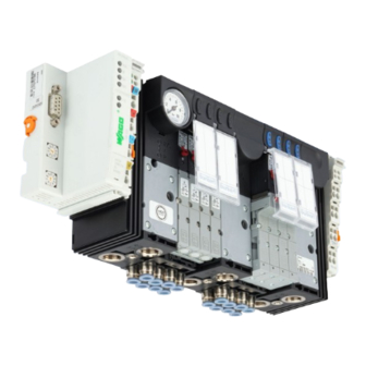
Type 8644 Product description PRODUCT DESCRIPTION Application range The valve island Type 8644 is built for decentralised use in industrial environments. Electronics and fluidics can be easily and efficiently combined due to the modular structure. DANGER! Risk of injury from electric shock. ▶ Switch off the power supply before working on the device or system. Secure against reactivation. ▶ Observe the applicable accident prevention and safety regulations for electrical devices. General description Fig. 1: Type 8644 AirLINE Wago The valve island Type 8644 is an electrical and pneumatic automation system that has been developed for use in control cabinets or switch boxes. -
Page 13: System Structure
Type 8644 Product description System structure Central control (e.g. PLC) Valve block Fieldbus node 1 (e.g. PROFIBUS Fieldbus Electrical Fieldbus node 2 base module Fieldbus node ... Fieldbus node n Pneumatic base module Fig. 2: Schematic representation of the Bürkert AIRLINE System english... - Page 14 Type 8644 Product description Left connection module Pressure gauge for operating pressure indication on the station 4-fold valve segment Intermediate feed 8-fold valve segment Right connection module Working ports Supply and vent connections Fig. 3: Representation of the modules of the Bürkert AIRLINE System Additional information and technical details on the electrical and fluidic components: Electrical modules see “7.2 Electrical connection modules”...
-
Page 15: Exploded View
Type 8644 Product description Exploded view 5.4.1 Exploded view - width per station 11mm, REV.1 Wago fieldbus node ME02 8-fold valve segment 2-fold valve segment ME02 2-fold valve segment ME02 ME02 Wago terminal module MP11 Bulkhead 6524 (2 x 3/2-way) 6524 6525 Cover plate 0460 Fig. -
Page 16: Exploded View - Width Per Station 11 Mm, Rev.2
Type 8644 Product description 5.4.2 Exploded view - width per station 11 mm, REV.2 Wago fieldbus node ME02 4-fold valve segment ME02 8-fold valve segment ME02 Wago terminal module ME02 MP16 Type 6524 (2x3/2-way) Type 6524 Type 6525 Accessories Type 6524 *PF34 Type 0460 Cover plate english... -
Page 17: Exploded View - Width Per Station 16 Mm, Rev.1
Type 8644 Product description 5.4.3 Exploded view - width per station 16 mm, REV.1 Wago fieldbus node ME03 4-fold valve segment 2-fold valve segment ME03 2-fold valve segment ME03 ME03 Wago terminal module MP12 Accessories 6526 6527 Cover plate 0461 Fig. 5: Exploded view - width per station 16 mm english... -
Page 18: Location And Description Of The Type Labels
Type 8644 Product description Location and description of the type labels 5.5.1 Valve island type label Device type Serial number Revision marking Order number Manufacture code Fig. 6: Location and description of a valve island type label (example) 5.5.2 UL type label Device type, internal code Supply voltage, current Operating pressure... -
Page 19: Valve Type Label
Type 8644 Product description 5.5.3 Valve type label Device type Mode of action permitted pressure range 6524 C 2,5—10bar 24VBA0,8W Voltage (± 10%), power W1XAW Production date (encrypted) 00123456 Order number Fig. 8: Location and description of a valve type label (example Type 6524) english... -
Page 20: Information On Compatibility And Revision Status
Type 8644 Product description Information on compatibility and revision status 5.6.1 Overview of revision statutes for the different widths per station Valve island width per station 11 mm REV.1 REV.2 • Electronic modules REV.1 • Electronic modules REV.1 • Pneumatic base modules REV.1 • Pneumatic base modules REV.2 • Connection modules REV.1 • Connection modules REV.2 • Solenoid valve types 6524 and 6525 REV.1: • Solenoid valve types 6524 and 6525 REV.2: 1 flange pattern for double valves: 1 flange pattern for double valves and single Type 6524 2 x 3/2-way... - Page 21 Type 8644 Product description Valve island width per station 16 mm REV.1 • Electronic modules REV.1 • Pneumatic base modules REV.1 • Connection modules REV.1 • Solenoid valve Types 6526, 6527 and 0461: 1 flange pattern for single valves: Type 6526 3/2-way Type 6527 5/2-way 1 flange pattern for pulse valves and bistable valves: Type 0461 5/2-way Type 0461 5/3-way english...
-
Page 22: Information On Revision 2 (Rev.2)
Type 8644 Product description 5.6.2 Information on Revision 2 (REV.2) The single valves of types 6524 and 6525, the pneumatic base modules and connection modules as well as the control cabinet base adaptation AirLINE Quick have been revised due to various optimisations. Compat- ibility must therefore be considered in the following cases: • Valve replacement • Expansion, repair or conversion of valve blocks Revision 2 (REV.2) only affects pneumatic components of the 8644 valve block. Not affected by the revision: – Electrical data – Configuration – External dimensions For further information see also - Chapters „7.2 Electrical connection modules“... -
Page 23: Technical Data
Type 8644 Technical data TECHNICAL DATA Operating conditions WARNING! Risk of injury. Malfunction when used outdoors. ▶ Do not use the device outdoors. ▶ Avoid heat sources which may cause the permissible temperature range to be exceeded. Ambient temperature 0...+50 °C Storage temperature –20...+60 °C Air humidity 75% on average, 85% occasionally... - Page 24 Type 8644 Technical data Max. current consumption Logic I_Log = I_Log_FBKN + Σ I_Module I_Log Power consumption in the 5 V logic range I_Log_FBKN Proportional current in the fieldbus node (see corresponding variant in Wago documentation) Further product-specific information about Wago fieldbus nodes / terminals can be found online at: www.wago.com Downloads Documentation WAGO I/O System 750 I_module Proportional current in the 5-V logic range of the basic electrical modules max.
-
Page 25: Technical Data Of The Valve Block
Type 8644 Technical data Technical data of the valve block Nominal operating mode Continuous operation (100% duty cycle) Degree of protection (in IP20 terminal version) Protection class III (according to VDE 0580) Total current depends on the electrical connection technology, expansion level and control unit Width per station 11 mm... - Page 26 Type 8644 Technical data Width per station 16 mm REV.1 REV.1 Variant C/D (3/2-way) L/N (5/3-way) Valve circuit function Type 6526 Type 0461*** Valve circuit H (5/2-way) Z (5/2-pulse) function Type 6527 Type 0461 Flow 700 l/min 500 l/min Pressure range 2...10 bar 2.5...7 bar (with P shutoff) Capacity 0.9 W...
-
Page 27: Electrical Data
Type 8644 Technical data Electrical data 6.4.1 Performance characteristics from the perspective of the overall system Left connection module (ME02, ME03) The left connection module is electronically passive logical no process image, therefore no address is required electronic no current consumption Fluidic left limitation of the valve block, left feed Central connection module (ME02, ME03) The intermediate feed is electronically passive logical... -
Page 28: Electrical Basic Module Me02 / 2-Fold Monostable, Me02 / 2-Fold 2 X Monostable
Type 8644 Technical data 6.4.2 Electrical basic module ME02 / 2-fold monostable, ME02 / 2-fold 2 x monostable Technical data ME02 / 2-fold ME02 / 2-fold monostable 2 x monostable Dimensions W x H x D 22 x 70.5 x 52 mm 22 x 70.5 x 52 mm Weight 38 g 38 g Storage temperature -20...+60° C -20...+60°... -
Page 29: Electrical Basic Module Me02 / 8-Fold Monostable, Me02 / 8-Fold 2 X Monostable
Type 8644 Technical data 6.4.3 Electrical basic module ME02 / 8-fold monostable, ME02 / 8-fold 2 x monostable Technical data ME02 / 8-fold ME02 / 8-fold monostable 2 x monostable Dimensions W x H x D 88 x 70.5 x 52 mm 88 x 70.5 x 52 mm Weight 94 g 94 g Storage temperature -20...+60° C -20...+60°... -
Page 30: Electronic Base Module Me02 / 2-Fold Bistable, Me02 / 8-Fold Bistable
Type 8644 Technical data 6.4.4 Electronic base module ME02 / 2-fold bistable, ME02 / 8-fold bistable Technical data ME02 / 2-fold ME02 / 8-fold bistable bistable Dimensions W x H x D 22 x 70.5 x 52 mm 88 x 70.5 x 52 mm Weight 38 g 94 g Storage temperature -20...+60° C -20...+60° C Load voltage DC 24 V DC 24 V... -
Page 31: Electronic Base Module Me03 / 2-Fold Monostable, Me03 / 2-Fold Bistable
Type 8644 Technical data 6.4.5 Electronic base module ME03 / 2-fold monostable, ME03 / 2-fold bistable Technical data ME03 / 2-fold ME03 / 2-fold monostable bistable Dimensions W x H x D 33 x 93 x 60 mm 33 x 93 x 60 mm Weight 54.4g 49.1g Storage temperature... -
Page 32: Electronic Base Module Me03 / 3-Fold 10 Mm Monostable, Me03 / 4-Fold Monostable
Type 8644 Technical data 6.4.6 Electronic base module ME03 / 3-fold 10 mm monostable, ME03 / 4-fold monostable Technical data ME03 / 3-fold ME03 / 4-fold 10mm monostable monostable Dimensions W x H x D 33 x 93 x 60 mm 66 x 93 x 60 mm Weight 51 g 91.2 g... -
Page 33: Structure And Function Of The Modules
Type 8644 Structure and function of the modules STRUCTURE AND FUNCTION OF THE MODULES Valve block The valve block consists of the follow assemblies: • Connection modules / feeds (common connections for supply, exhaust air and auxiliary pilot air), • Valve segments (working ports, various valves). Intermediate feed Left connection... -
Page 34: Electrical Connection Modules
Type 8644 Structure and function of the modules Electrical connection modules Aperture variant with pressure gauge Electrical connection module Type ME02/ME03 (left, right) Pneumatic feed Interface to the electrical section of the 11 mm: MP11 for REV.1, MP16 for REV.2 automation system 16 mm: MP12 (fieldbus nodes; electrical modules/... -
Page 35: Electronic Base Modules
Type 8644 Structure and function of the modules Electronic base modules The electronic base module is connected to the neighbouring modules via its electrical interface. In this way, it receives both the power supply and the control signals for the valves on the valve slots. Electronic base modules and therefore the valve segments can be controlled like digital output modules / terminals. - Page 36 Type 8644 Structure and function of the modules Combination modules (electronic base module / valve) Base module type Width per Valve slots Valve type Mode of action station ME02 2-fold 11 mm 6524 3/2-way monostable 6525 5/2-way 2-fold 11 mm 0460 5/3-way bistable 5/2-way pulse 2-fold 11 mm 6524 2 x 3/2-way 2 x monostable...
-
Page 37: Electronic Base Module Me02 / 2-Fold Monostable
Type 8644 Structure and function of the modules 7.3.1 Electronic base module ME02 / 2-fold monostable Structure An electronic base module consists of a distribution module (backplane bus) and a function module. Both modules are contacted by a 14-pin board-to-board connector. Combination options with valve types Base module type Width per... -
Page 38: Electronic Base Module Me02 / 2-Fold 2 X Monostable
Type 8644 Structure and function of the modules 7.3.2 Electronic base module ME02 / 2-fold 2 x monostable Structure An electronic base module consists of a distribution module (backplane bus) and a function module. Both modules are contacted by a 14-pin board-to-board connector. Combination options with valve types Base module type Width per... -
Page 39: Electronic Base Module Me02 / 8-Fold Monostable
Type 8644 Structure and function of the modules 7.3.3 Electronic base module ME02 / 8-fold monostable Structure An electronic base module consists of a distribution module (backplane bus) and a function module. Both modules are contacted by a 14-pin board-to-board connector. Combination options with valve types Base module type Width per... -
Page 40: Electronic Base Module Me02 / 8-Fold 2 X Monostable
Type 8644 Structure and function of the modules 7.3.4 Electronic base module ME02 / 8-fold 2 x monostable Structure An electronic base module consists of a distribution module (backplane bus) and a function module. Both modules are contacted by a 14-pin board-to-board connector. Combination options with valve types Base module type Width per... -
Page 41: Electronic Base Module Me02 / 2-Fold Bistable
Type 8644 Structure and function of the modules 7.3.5 Electronic base module ME02 / 2-fold bistable Structure An electronic base module consists of a distribution module (backplane bus) and a function module. Both modules are contacted by a 14-pin board-to-board connector. Combination options with valve types Base module type Width per... -
Page 42: Electronic Base Module Me02 / 8-Fold Bistable
Type 8644 Structure and function of the modules 7.3.6 Electronic base module ME02 / 8-fold bistable Structure An electronic base module consists of a distribution module (backplane bus) and a function module. Both modules are contacted by a 14-pin board-to-board connector. Combination options with valve types Base module type Width per... -
Page 43: Electronic Base Module Me03 / 2-Fold Monostable
Type 8644 Structure and function of the modules 7.3.7 Electronic base module ME03 / 2-fold monostable Structure An electronic base module consists of a distribution module (backplane bus) and a function module. Both modules are contacted by a 14-pin board-to-board connector. Combination options with valve types Base module type Width per... -
Page 44: Electronic Base Module Me03 / 2-Fold Bistable
Type 8644 Structure and function of the modules 7.3.8 Electronic base module ME03 / 2-fold bistable This base module is only available for devices of revision 1 (REV.1): see „5.6.1 Overview of revision statutes for the different widths per station“. Structure An electronic base module consists of a distribution module (backplane bus) and a function module. Both modules are contacted by a 14-pin board-to-board connector. -
Page 45: Electronic Base Module Me03 / 3-Fold 10 Mm Monostable
Type 8644 Structure and function of the modules 7.3.9 Electronic base module ME03 / 3-fold 10 mm monostable Structure An electronic base module consists of a distribution module (backplane bus) and a function module. Both modules are contacted by a 14-pin board-to-board connector. Combination options with valve types Base module type Width per... -
Page 46: Electronic Base Module Me03 / 4-Fold Monostable
Type 8644 Structure and function of the modules 7.3.10 Electronic base module ME03 / 4-fold monostable Structure An electronic base module consists of a distribution module (backplane bus) and a function module. Both modules are contacted by a 14-pin board-to-board connector. Combination options with valve types Base module type Width per... -
Page 47: Pneumatic Connection Modules
Type 8644 Structure and function of the modules Pneumatic connection modules Feeds in the form of pneumatic connection modules form the fluid interface between the supply line and the internal supply structure. The fluid is passed from one valve segment to the next via the feed. To ensure that the supply pressure over the entire route remains almost constant, additional feeds may be required. It is recommended to set one after 24 (ME02) or 16 (ME03) valve positions. By using intermediate feeds, seg- ments can also be created if the pneumatic channels between individual valve segments are closed. - Page 48 Type 8644 Structure and function of the modules Variants Width per station Pressure port (P) 1 Port X Exhaust air port (R/S) 3/5 11 mm G 1/4 G 1/4 16 mm G 3/8 G1/8 G 3/8 • Variant available with and without pressure gauge Port X Operation Pin assignment from X Standard Exhaust air, pilot valve Auxiliary pilot air Port for auxiliary pilot air (operation with auxiliary pilot air is optional)
-
Page 49: Pneumatic Base Modules
Type 8644 Structure and function of the modules Pneumatic base modules The pneumatic base module is part of the valve unit. It carries the valves, is used for pneumatic supply and venting of the valves and provides the pneumatic working outputs. Various port and equipment options are available (see data sheet). -
Page 50: Valves
Type 8644 Structure and function of the modules Valves 7.6.1 Valves Type 6524 and Type 6525 for valve islands width per station 11 mm Type 6524 Type 6525 Manual override Manual override Manual override 5/2-way valve 3/2-way valve 2x3/2-way valve Fig. - Page 51 Type 8644 Structure and function of the modules 7.6.1.1 Fluidic connection single valves Type 6525 Type 6524 Make the pressure supply as large as possible! X* – pilot exhaust air Fig. 26: Fluid connection single valves Type 6524 and Type 6525 7.6.1.2 Fluidic and electrical connection double valves Type 6524...
- Page 52 Type 8644 Structure and function of the modules 7.6.1.3 Exchange valve types 6524 and 6525 DANGER Risk of injury due to pressure change. Actuators can change their position when the pressure changes, leading to injuries and material damage. Secure the actuators against adjusting before working on the device or system. ►...
- Page 53 Type 8644 Structure and function of the modules 30 Ncm 20 Ncm 20 Ncm 30 Ncm Fig. 28: Tightening the screws when replacing valve types 6524 and 6525 english...
- Page 54 Type 8644 Structure and function of the modules 7.6.1.4 Valve Type 6524 and Type 6525: Differentiating features between REV.1 and REV.2 REV.1: The single valves of Type 6524 3/2-way and Type 6525 5/2-way have the same flange pattern towards the pneumatic base module. This single valve flange pattern differs from that of the double valve Type 6524 2x3/2-way. REV.2: Compared to the REV.1, the flange patterns of the valves for the pneumatic base modules have been stan- dardised. The single valves 3/2-way and 5/2-way as well as the double valves 2x3/2-way now have the same/unified pneumatic flange pattern.
-
Page 55: Valves Type 0460 For Valve Islands Width Per Station 11 Mm
Type 8644 Structure and function of the modules 7.6.2 Valves Type 0460 for valve islands width per station 11 mm Manual override Fig. 31: Valve Type 0460, width per station 11 mm Valve Type 0460 consists of 2 pilot valves and 1 pneumatic slide valve. The operating principle allows the switching of high pressures together with low power consumption and fast switching times. The valves offer 5/2-way impulse and 5/3-way functions and are equipped with manual overrides as standard. -
Page 56: Valves Type 6526 And Type 6527 For Valve Islands Width Per Station 16 Mm
Type 8644 Structure and function of the modules 7.6.3 Valves Type 6526 and Type 6527 for valve islands width per station 16 mm Type 6526 Type 6527 Manual override Manual override 3/2-way valve 5/2-way valve Fig. 32: Valves Type 6526 (3/2-way valve) and Type 6527 (5/2-way valve) Type 6526 is a 3/2-way valve, Type 6527 is a 5/2-way valve. The valves consist of a flipper solenoid valve as a pilot control and a pneumatic seat valve as an amplifier. They are monostable and equipped with manual override as standard. - Page 57 Type 8644 Structure and function of the modules 7.6.3.2 Exchange valves Type 6526 and Type 6527 DANGER Risk of injury due to pressure change. Actuators can change their position when the pressure changes, leading to injuries and material damage. Secure the actuators against adjusting before working on the device or system. ►...
-
Page 58: Valves Type 0461 For Valve Islands Width Per Station 16 Mm
Type 8644 Structure and function of the modules 7.6.4 Valves Type 0461 for valve islands width per station 16 mm Manual override Fig. 35: Valve Type 0461, width per station 16 mm Valve Type 0461 consists of 2 pilot valves and 1 pneumatic slide valve. The operating principle allows the switching of high pressures together with low power consumption and fast switching times. -
Page 59: Installation And Start-Up Of The Valve Island In The Control Cabinet
Type 8644 Installation and start-up of the valve island in the control cabinet INSTALLATION AND START-UP OF THE VALVE ISLAND IN THE CONTROL CABINET Safety instructions DANGER Risk of explosion. For systems in the explosion-proof areas, which are installed in a control cabinet, the following must be ensured: The control cabinet must be approved for use in explosion-proof areas. -
Page 60: Removing The Transport Lock From The Valve Block
Type 8644 Installation and start-up of the valve island in the control cabinet Removing the transport lock from the valve block The valve block is mounted on a standard rail for transport security. It must be removed from this standard rail for installation in the control cabinet. -
Page 61: Installation On Standard Rail
Type 8644 Installation and start-up of the valve island in the control cabinet Installation on standard rail ATTENTION To ensure the best possible EMC protection, ground the standard rail with low impedance. ► Prior to installation in the control cabinet, check whether the standard rail is firmly anchored in the con- ► trol cabinet. The valve block must be freely accessible at the top. When installing the standard rail in the control cabinet, consider that the valve block requires a minimum distance of 3 cm from the top edge of the control cabinet (“Fig. -
Page 62: Fluidic Installation
Type 8644 Installation and start-up of the valve island in the control cabinet Fluidic installation DANGER Risk of injury from high pressure. Before loosening lines and valves, turn off the pressure and vent the lines. ► Close open connections that are not required with suitable fastener elements. ► Connections for pilot exhaust air (x) must not be closed. ►... -
Page 63: Pneumatic Installation Of The Valve Units
Type 8644 Installation and start-up of the valve island in the control cabinet 8.4.2 Pneumatic installation of the valve units ATTENTION With 3/2-way valves, the upper ports remain open. 1 (upper connections) 2 (lower connections) Fig. 39: Pneumatic pin assignment base module 3/2-way valve 5/2-way valve 2x3/2-way valve... -
Page 64: Installation With Airline Quick (Only Valve Islands Width Per Station 11 Mm)
Type 8644 Installation and start-up of the valve island in the control cabinet Installation with AirLINE Quick (only valve islands width per station 11 mm) When using the “AirLINE Quick” control cabinet base adaptation, the device is mounted on the control cabinet base using a solid metal plate. -
Page 65: Installation Of Airline Quick
The break-out can be done, for example, with a laser or a punch. The assignment of pneumatic ports and the dimensions of the flange patterns can be found online at → „Additional manual Type 8640 8644 | AirLINE Quick, Assignment of country.burkert.com→8644 the pneumatic connections“ ATTENTION The break-out on the control cabinet must be burr-free to avoid damage to the seal between the AirLINE ►... -
Page 66: Dimensions Of The Flange Patterns For Airline Quick
Type 8644 Installation and start-up of the valve island in the control cabinet 8.5.3 Dimensions of the flange patterns for AirLINE Quick Control cabinet inner wall t>= 1.5 Ø 5.3 ± 0.2 R 6.5 only with O= 6 and O = 10 (O = number of holes) Space required for external reinforcement frame Fig. -
Page 67: Assignment Of The Pneumatic Connections For Airline Quick
Type 8644 Installation and start-up of the valve island in the control cabinet 8.5.4 Assignment of the pneumatic connections for AirLINE Quick Example Type 8640 Pneumatic connection Valve outlet AirLINE Quick 2x3/2-way / Type 6524 5/2-way / Type 6525 Valve type 3/2-way / Type 6524 Electrical installation DANGER! Risk of injury from electric shock. -
Page 68: Maintenance, Troubleshooting
Type 8644 Maintenance, troubleshooting MAINTENANCE, TROUBLESHOOTING Safety instructions DANGER! Risk of injury due to high pressure and escaping medium. ▶ Switch off the pressure before working on the device or system. Vent or drain the pipes. Risk of injury from electric shock. ▶ Switch off the power supply before working on the device or system. Secure against reactivation. ▶ Observe the applicable accident prevention and safety regulations for electrical devices. WARNING! Risk of injury due to improper maintenance work! ▶ Maintenance may only be carried out by authorised technicians and with the appropriate tools! Risk of injury due to unintentional activation of the system and uncontrolled restart! ▶... -
Page 69: Maintenance Of Components
Type 8644 Maintenance, troubleshooting Fault Possible cause Remedy Valves switch with a Pressure supply insufficient or not → Make the pressure supply as high as delay or blow off at available possible (also for upstream devices such as the exhaust ports pressure regulators, maintenance units, on/ off valves etc.) Minimum operating pressure ≥ 2.5 bar Valves are not in the home →... -
Page 70: Start-Up
Type 8644 Start-up START-UP 10.1 Safety instructions WARNING! Risk of injury due to improper operation! Improper operation may result in injuries as well as damage to the device and the surrounding area. ▶ Before start-up, ensure that the operating personnel are aware of and have completely understood the contents of the operating instructions. -
Page 71: Selection Of Modules In The Gsd File
Type 8644 Start-up 10.3.1 Selection of modules in the GSD file The module names of the different electronic base modules in the GSD file can be found in the table below. Width per station Module name Entry in GDSD file ME02 / 2-fold monostable Bürkert 8644 monostable 2 DO *Bürkert 8644 monostable 2 DO ME02 / 2-fold 2 x Bürkert 8644 monostable 4 DO 11 mm monostable *Bürkert 8644 monostable 4 DO ME02 / 8-fold monostable... -
Page 72: Accessories, Spare Parts
Type 8644 Accessories, spare parts ACCESSORIES, SPARE PARTS CAUTION Risk of injury and/or damage due to incorrect parts. Incorrect accessories and unsuitable spare parts may cause injuries and damage the device and the sur- rounding area. Use only original accessories and original spare parts from Bürkert. ► The article numbers of the solenoid valve types 6524, 6525 and 0460 and the corresponding cover plates can be found in the data sheets for these types. -
Page 73: Packaging, Transport, Storage
Store the device in a dry and dust-free location. ► Storage temperature –20...+60 °C. ► ENVIRONMENTALLY FRIENDLY DISPOSAL Follow national regulations regarding disposal and the environment. ► Collect electrical and electronic devices separately and dispose of them as special waste. ► Further information at country.burkert.com. english...
Need help?
Do you have a question about the AirLINE 8644 and is the answer not in the manual?
Questions and answers