Burkert 8741 Operating Instructions Manual
Mass flow meter mfm / mass flow controller mfc
Hide thumbs
Also See for 8741:
- Operating instructions manual (44 pages) ,
- Operating instructions manual (69 pages)
Table of Contents
Advertisement
Quick Links
Advertisement
Table of Contents
Troubleshooting

Related Manuals for Burkert 8741


Summary of Contents for Burkert 8741
- Page 1 Type 8741, 8742 büS / CANopen Mass Flow Meter (MFM) / Mass Flow Controller (MFC) Massendurchflussmesser (MFM) / Massendurchflussregler (MFC) Débitmètre massique (MFM) / Régulateur de débit massique (MFC) Operating Instructions Bedienungsanleitung Manuel d‘utilisation...
- Page 2 We reserve the right to make technical changes without notice. Technische Änderungen vorbehalten. Sous réserve de modifications techniques. © Bürkert SAS, 2014 – 2022 Operating Instructions 2206/05_EU-ML_00810383 / Original EN...
-
Page 3: Table Of Contents
Type 8741 / 8742 Table of contents Fluid data ..............14 OPERATING INSTRUCTIONS ..........5 Electrical data ............. 15 1.1 Definition of terms ............5 Markings ..............16 Symbols used ............... 5 INSTALLATION ..............17 INTENDED USE ..............6 Safety instructions ............17 Versions with explosion protection ....... - Page 4 Type 8741 / 8742 10 MAINTENANCE ..............34 10.1 Maintenance for operation with heavily con- taminated media ............34 10.2 Cleaning and recalibration at the factory ....35 11 DEVICE STATUS/TROUBLESHOOTING ......36 11.1 Display of the device status ........36 11.2 Troubleshooting ............
-
Page 5: Operating Instructions
Type 8741 / 8742 Operating instructions OPERATING INSTRUCTIONS CAUTION! The Operating Instructions describe the entire life cycle of the Warns of possible danger! device. Please keep the Operating Instructions in a safe place, ▶ Failure to observe this warning can result in substantial or accessible to all users and any new owners. -
Page 6: Intended Use
Improper use of the device may be a hazard to people, nearby equipment and the environment. Danger of explosion in the event of improper use in poten- MFM type 8741 / 8742 is used exclusively to measure the mass tially explosive areas! flow of clean dry gases. -
Page 7: Basic Safety Information
Type 8741 / 8742 Basic safety information BASIC SAFETY INFORMATION Various dangerous situations. To avoid personal injury, take care: These safety instructions do not take the following into account: ▶ Not to operate the device without the factory installed input •... -
Page 8: General Information
F-67220 TRIEMBACH-AU VAL The addresses of our international sales offices are available on the internet at: country.burkert.com. Warranty The warranty is conditional on compliant use of the device in observance of the operating conditions specified in this manual. Information on the Internet Operating manuals and data sheets for the type 8741/8742 can be found online at: country.burkert.com. English... -
Page 9: Description Of The Device
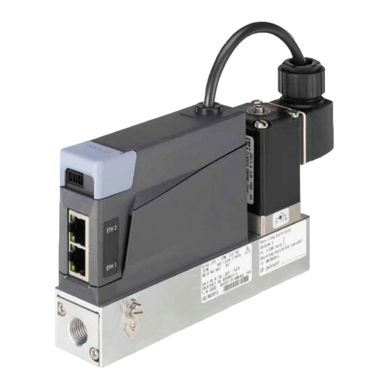
* The removable connector is part of the device and device earthing ** For cable shielding and earthing of the device 11. Fluid connection Fig. 1: Design of the device type 8741 Fig. 2: Design of the device type 8742 English... -
Page 10: General Description
Type 8741 / 8742 Description of the device General description Operation of the MFC (Mass Flow Controller) The device is available in two basic versions. Design: • As a Mass Flow Meter (MFM) the device measures the mass flow of the gases for which it has been calibrated. • The mass flow is measured by a sensor. - Page 11 Type 8741 / 8742 Description of the device The measured mass flow value is transmitted to an external device Setpoint via a digital output (fieldbus). The setpoint (w) is transmitted digitally via the fieldbus interface. For control of a system where quick flow-rate changes are not per- In order to obtain a dynamic or quiet measured-value mitted, a ramp function can be activated. This enables the param- output signal, the damping of this signal can be adjusted by eters for an ascending or descending setpoint to be set separately.
-
Page 12: Operation Of The Sensor In The Device
Type 8741 / 8742 Description of the device The solenoid valve used for an MFC is a direct-acting, normal- Zero point shut-off: ly-closed proportional valve. The nominal diameter of the solenoid A zero point shut-off is included to ensure the sealing function... -
Page 13: Technical Data
Type 8741 / 8742 Technical data TECHNICAL DATA Special operating conditions with ATEX certification: See the ATEX supplement for the type 8742. Permissible temperatures Conformity Ambient temperature: −10 °C...+50 °C The device complies with the EU-directives according to the EU Medium temperature: −10 °C...+70 °C declaration of conformity (if applicable). for oxygen: −10 °C...+60 °C Standards Permissible humidity: < 95 %, non-condensing The standards used to demonstrate conformity with the Directives... -
Page 14: Mechanical Data
Type 8741 / 8742 Technical data Fluid data 6.4.1 Quality of the operating medium For the required measurement and control precision and to meet the Calibration medium Operating fluid or air safety requirements, the gas or gas mixture must meet the following Mass flow range 0.01...80... -
Page 15: Electrical Data
Type 8741 / 8742 Technical data Electrical data • flange connection on the bottom of the device (used for mounting on a block). Operating voltage MFC: 2 4 V DC ± 10 %; ∆p [mbar] residual ripple < 2 % MFM: 24 V DC ± 10 % Max. power consumption MFM : < 1 W MFC: Dependent on the proportional valve used, see name plate in chapter 6.8.2... -
Page 16: Markings
Type 8741 / 8742 Technical data Markings 6.8.2 Standard name plate WARNING! 8741 24V ... 9W [5,5W] Risk of injury caused by pressure, medium escape! IP20 NEC Class 2 only 5,0 Nl/min Air Important device-specific data are indicated on the name plate 10,0 Nl/min Air and calibration plate. -
Page 17: Installation
Type 8741 / 8742 Installation INSTALLATION 11. Serial number 12. Category of the device Safety instructions 13. Communication interface DANGER 14. Nominal flow rate (Qnominal), units and operating medium gas 2 Danger due to high pressure in the installation/device. 15. Nominal flow rate (Qnominal), units and operating medium gas 1 ▶ Before working on the installation or device, cut the pressure 16. -
Page 18: Before Installation
Type 8741 / 8742 Installation Fluid system installation Sequence of steps for installing the device: 1. Mechanical installation DANGER! Observe the installation position! 2. Fluid system installation Danger due to high pressure in the installation/device. ▶ Before working on the installation or device, cut the pressure 3. - Page 19 Type 8741 / 8742 Installation → → Cut the line squarely [1] and deburr [2]. Fix the sealing ring [C] and the connecting thread [B] to the device (tightening torque 25...28 Nm). Fig. 8: Cutting the pipe and deburring Fig. 10: Fix the sealing ring and screw on the connecting thread → Remove the protective cap with which the port is closed.
-
Page 20: Installation And Removal Of The Impact Protection Cover And Blind Plug On Type 8742
Type 8741 / 8742 Installation → Installation and removal of the Tighten the lock nut with an open-end spanner so that the connection is leak tight (tightening torque 25...28 Nm). impact protection cover and blind plug on type 8742 The impact protection cover is designed for use in an Ex. area. When the device is used in a non-Ex. -
Page 21: Setting Up The Fieldbus
Mounting screws (M3 cylinder head screws with allen key socket) Locking hooks Fig. 14: Switch for setting the fieldbus, type 8741. The configured fieldbus is accepted by the device after a Fig. 13: Attaching the impact protection cover restart. → Devices with a software version from A. 14.00.00 Tighten the mounting screws (at a torque between 0.8 Nm...1 Nm, i.e. 0.59 lbf·ft...0.74 lbf·ft). - Page 22 Type 8741 / 8742 Installation → Go to menu General settings Parameters büS The configured fieldbus is accepted by the device after a Advanced mode. restart. → Choose the operating mode of the digital communication. → Devices with a software version from A. 14.00.00 Restart the device. On the devices with a software version from A. 14.00.00, you The operating mode of the fieldbus is changed.
-
Page 23: Electrical Installation
Type 8741 / 8742 Installation Electrical installation 7.7.1 Connect the power supply and communication cable, type 8741 DANGER Electrical input assignments: Risk of injury from electric shocks. Screw terminals, ▶ Before working on the installation or device, switch off the 1 2 3 4 4-pin power and ensure that it cannot be reactivated. - Page 24 Type 8741 / 8742 Installation Cable assembly: (See Fig. 17) 7.7.2 Connect the power supply and → communication cable, type 8742 Remove the insulation sheath over a length of approx. 25 mm. Electrical input assignments: → Shorten the cable shielding to the required length (see M12 plug, 5-pin engraved symbols on the inside of the protective cover).
-
Page 25: Connecting The Functional Earth
Type 8741 / 8742 Installation There are two screws that can be used for either the functional 5- pin M12 female earthing or the earthing of the type 8741 (M3 screw at a torque connector between 0.6 Nm...0.8 Nm, i.e. 0.44 lbf·ft...0.59 lbf·ft; M4 screw at a torque between 1.8 Nm...2 Nm, i.e. 1.33 lbf·ft...1.47 lbf·ft). Type 8741 Type 8742... -
Page 26: Connecting The Cable Screen
Type 8741 / 8742 Commissioning Connecting the cable screen COMMISSIONING Connection of the cable screen to screw M3: Safety instructions NOTE! Requirements for the proper function of the device! WARNING! The cable shield must be attached to functional earth FE on Danger of injury from improper operation! the two outermost devices. -
Page 27: Operation And Function
Type 8741 / 8742 Operation and function OPERATION AND FUNCTION Device status LED The device has an LED to display the device status, the colour and Safety instructions status change according to Namur NE 107. If more than one device status exists simultaneously, the device WARNING! status with the highest priority is displayed. -
Page 28: Setting Up The Fieldbus
Type 8741 / 8742 Operation and function Replaceable configuration memory Description Meaning according The device has a replaceable configuration memory, on which the to NE 107 device-specific data is stored. Blue Maintenance The device is still measuring (MFM) or in The device is delivered with the configuration memory inserted. required controlled operation (MFC), however a function is briefly restricted. The configuration memory enables the exchange of specific data → Do the required maintenance operation. - Page 29 Type 8741 / 8742 Operation and function 9.5.1 Replacing the configuration memory 1. Grip the configuration Flat-nose memory with flat nose pliers • Before replacing the configuration memory of the type pliers. 8742, remove the blind plug (see chapter 7.5). 2. Insert the configuration Electronic • Pay attention to the direction of insertion: see Fig. 23. memory at an angle. board 3.
-
Page 30: Functions
Type 8741 / 8742 Operation and function Functions Cross-sectional drawing: Configuration memory in the device 9.6.1 AUTOTUNE function Function optimisation of the MFC control parameters. For the MFC, the AUTOTUNE function is set at the factory. This is done at the operating pressure and with the calibration medium specified in the calibration pro- tocol. - Page 31 Type 8741 / 8742 Operation and function 9.6.2 In the büS network, other participants WARNING! process the process values Danger from flowing gas! The device can receive and process the process values from other While the AUTOTUNE function is running, the gas flow may be büS participants in a büS network.
- Page 32 Type 8741 / 8742 Operation and function 9.6.4 User-defined calibration AUTOMATIC function: If the AUTOMATIC setpoint source is selected, a standard setpoint The devices are always delivered with a calibration by the is used which is specified via the CANopen or büS fieldbus. This manufacturer. standard setpoint can be manipulated by other fieldbus participants. Using the "Bürkert Communicator" software, a user-defined cali- If different fieldbus participants simultaneously specify a setpoint for the device, it is always the most recent value that is used for control.
- Page 33 Type 8741 / 8742 Maintenance MAINTENANCE The inhibit time is changed via • a setting in the "Bürkert Communicator" software (see The device is maintenance-free, provided that no heavily con- chapter 12.3 Bürkert Communicator (PC software)) or taminated media are used and that it is operated according to the •...
-
Page 34: Maintenance
Type 8741 / 8742 Maintenance 10.1.1 Cleaning the stainless steel mesh filter WARNING! Item Description Risk of injury from malfunction and failure by opening the housing! Screw There are sensitive parts inside the device to control the flow and Inlet flange plate for measurement of the flow rate. O-ring ▶ Do not open the device housing. O-ring ▶ Only the cleaning and maintenance work described in this Stainless steel mesh filter manual may be carried out on the device. -
Page 35: Cleaning And Recalibration At The Factory
Type 8741 / 8742 Device status/Troubleshooting → DEVICE STATUS/ The O-Ring [3] remains in the device. → Remove the O-ring [4] and the stainless steel mesh filter [5] TROUBLESHOOTING using a pair of tweezers. → Clean the stainless steel mesh filter [5]. 11.1 Display of the device status Do not clean with tap water! The device has an LED to display the device status, the colour and Clean with acetone, isopropanol or compressed air. -
Page 36: Device Status/Troubleshooting
Type 8741 / 8742 Device status/Troubleshooting Description What to do? Description What to do? according to according to NE 107 NE 107 Faulty sensor. Orange MANUAL SETPOINT or Maintenance is needed – CONTROL MODE as Faulty memory. Contact the manufacturer. setpoint source. - Page 37 Type 8741 / 8742 Device status/Troubleshooting 11.2 Troubleshooting Description What to do? according to Problem Possible cause What to do? NE 107 The Namur The power supply is Use a power supply with Yellow Other fieldbus parti- Assign the participant an LED goes out intermittently dropping sufficient power output.
- Page 38 Type 8741 / 8742 Device status/Troubleshooting Problem Possible cause What to do? Problem Possible cause What to do? Device does not The value to be adopted Assign the value to be Setpoint at 0 % The operating pressure Reduce the operating adopt the values...
-
Page 39: Accessories /Spare Parts
Electrical Accessories application. Item Order code • Compression or olive-type fittings are suitable for many applica- 4-pin plug connector for type 8741 565876 tions, however alternative fittings can also be used. 4-pin plug connector for type 8741 with 566066 integrated 120-ohm terminal resistor 12.2.1 Compression fittings büS stick set (including power supply) 772426 The following compression fittings are available from Bürkert for büS stick set (without power supply) 772551 the device. -
Page 40: Bürkert Communicator (Pc Software)
• ATEX supplement for the type 8742 with ATEX certification The "Bürkert Communicator" PC software enables communi- (download from country.burkert.com) cation with the device. • Supplement for type 8741 and type 8742 (download from country.burkert.com) "Bürkert Communicator" software runs under Windows. • Cabling guide for EDIP (download from country.burkert.com) It needs to communicate with the device via a USB interface, büS stick... -
Page 41: Decommissioning
Risk of injury from electric shocks. ▶ Before working on the installation or device, switch off the power and ensure that it cannot be reactivated. Fluid connections type 8741 and 8742 ▶ Observe the applicable accident protection and safety regu- lations for electrical equipment. WARNING! Risk of injury from improper dismantling! ▶... -
Page 42: Transport, Storage, Disposal
Type 8741 / 8742 Transport, storage, disposal TRANSPORT, STORAGE, Procedure: → Relieve the operating medium pressure in the system. DISPOSAL → Flush the device with a neutral medium (e.g. nitrogen) NOTE! → Relieve the flushing medium pressure in the system. Transport damage! → Switch off the power. Damage can be caused to insufficiently protected devices in → For type 8741 only: transport. -
Page 43: Returning The Device
Type 8741 / 8742 Returning the device RETURNING THE DEVICE No work or tests will be carried out on the device until a valid Contamination Declaration has been received. The Contamination Declaration can be downloaded from our homepage or requested from your local Bürkert sales office. - Page 44 Type 8741 / 8742 Returning the device English...
- Page 46 www.burkert.com...
Need help?
Do you have a question about the 8741 and is the answer not in the manual?
Questions and answers