
Related Manuals for Burkert 8008


Summary of Contents for Burkert 8008
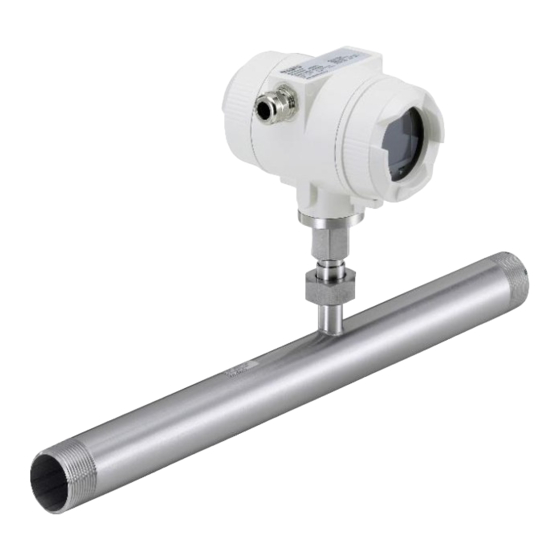
- Page 1 EN – English Instruction manual Consumption counter Typ 8008 with Display, 4 ... 20 mA and pulse output (galv. isolated) Stationary Flow and consumption measurement for compressed air and gases Type 8008 English V1.17...
-
Page 2: Foreword
Foreword Dear customer, thank you very much for deciding in favour of the Typ 8008. Please read this installation and operation manual carefully before mounting and initiating the device and follow our advice. A riskless operation and a correct functioning of the... -
Page 3: Table Of Contents
Scaling Analogue output Comprssed Air ..............8 Installation Description ....................9 Pipe/tube requirements ......................9 Inlet / outlet runs ........................9 Installation of Typ 8008 ...................... 10 Displayhead Position ......................10 Flow measuring ranges ....................11 Flow for different gases....................... 11 Dimensions ........................12... - Page 4 Status / Error messages ...................31 10.1 Status messages ........................31 10.2 Error messages ........................32 Maintenance ......................33 Cleaning of the sensor head ..................33 Re-Calibration ......................33 Spare parts and repair ....................33 Calibration .........................33 Warranty ........................34 Typ 8008 English V1.17 Page 4 of 34...
-
Page 5: Safety Instructions
We are also not liable for consequential damage resulting from the delivery, capability or use of this device. We offer you to take back the instruments of the instruments family Typ 8008 which you would like to dispose of. -
Page 6: Instruments Description
Instruments description 2 Instruments description The Typ 8008 is a compact consumption counter for compressed air and gases. Special features: - Optimum accuracy due to compact design - Integrated Inlet/ outlet section - Less flow due to measuring section - Intgrated Display showing Flow, consuption, velocity and temperature - Units free selectable. -
Page 7: Technical Data
R 1/4", R1/2", R3/4", R1", R 1 1/4" R1 1/2", R 2” DIN EN Mounting thread: 10226 (ISO 7-1) Material: Stainless steel 1.4301 / 1.4404 Version with flange DIN EN 1092-1: Stainless steel 1.4404 Protection calss: IP65 ‘* m.v. = measured values f.s. = full scale Type 8008 English V1.17... -
Page 8: Scaling Analogue Output Comprssed Air
Extended 0...290 m³/h Maximum 0...355 m³/h Low Speed 0...140 m³/h Standard 0...265 m³/h 4… 20 mA = TYP 8008 with integrated 1 1/4" meas. section Extended 0...530 m³/h Maximum 0...640 m³/h Low Speed 0...195 m³/h Standard 0...365 m³/h 4… 20 mA = TYP 8008 with integrated 1 1/2"... -
Page 9: Installation Description
Attention: The dimensions of the Type 8008 consumption counter measuring sections do not fullfill the required minimum lengths of the input and outlet runs. Please ensure recommended in - and outlet distances, dimensions of measuring sections see page 12 and 13. -
Page 10: Installation Of Typ 8008
Installation Installation of Typ 8008 The sensor Typ 8008 is pre-supplied with the measuring section. An installation at customer site is only allowed in the unpressurized state of the system The connecting nut is tightened to a torque of 25 -30 Nm. -
Page 11: Flow Measuring Ranges
Other gases on request Please note: The consumption sensor Type 8008 corresponds with the current state of technology and basically it can be used in any flammable and non-flammable gases. If this consumption sensor is used for measurement of flammable gases (e.g. natural gas and so on) we expressly would like to point out that the sensor has no DVGW admission, however, it can be used for measurements in natural gas. -
Page 12: Dimensions
26,9 / 21,7 179,8 166,3 Typ 8008 1“ R 1“ DN 25 33,7 / 27,3 183,2 166,3 Typ 8008 1 1/4" DN 32 42,4 / 36,0 187,5 166,3 R 1 1/4" Typ 8008 1 1/2“ R 1 1/2“ DN 40... -
Page 13: With Measurement Section And Flange (Material Stainless Steel 1.4404)
166,3 4 x 14 Typ 8008 1“ DN 25 33,7 / 27,3 223,8 166,3 4 x 14 Typ 8008 1 1/4" DN 32 42,4 / 36,0 263,3 166,3 4 x 18 Typ 8008 1 1/2“ DN 40 48,3 / 41,9... -
Page 14: Electrical Wiring
DIP Switch to “On”. It must be ensured that the connection plugs are still plugged and the gasket is installed correctly, see also chapter 4.1. Alternatively, a 120R resistor can be installed in the plug between pin 2 and pin Type 8008 English V1.17... -
Page 15: Operation
Operation 9 Operation “OK“ ( ) “Up“ ( The operation of the Typ 8008 is done by the two capacitive key buttons Up ( ) and Enter ( Type 8008 English V1.17... -
Page 16: Initialization
Operation Initialization After switching on the Typ 8008, the initialized screen is displayed followed by the main menu. Flow Sensor Main menu *** VA 520 *** *** Typ 8007 *** Gastype / Status message HW Version Modbus ID Page-no. SW Version ... -
Page 17: Settings
„ “ with key and then confirm it with “OK“. 9.3.1.1 Input / change tube diameter For Typ 8008 not adjustable (suspended) as voted on included measuring section with corresponding pipe diameter. Typ 8008 English V1.17 Page 17 of 34... -
Page 18: Input / Change Consumption Counter
In case the quantity of units selectable are not presentable on one page, pleas move to next „<<“ page by pressing Confirm selection by pressing 2x „OK“. Procedure for all 4 measurement variables is analogous. Typ 8008 English V1.17 Page 18 of 34... -
Page 19: Definition Of The Reference Conditions
„“ By pressing the position value is incremented by 1. Complete with "OK" activate next number position. Procedure for changing the reference temperature is the same. Typ 8008 English V1.17 Page 19 of 34 Under point "Filtertime" together with the... - Page 20 Setup Sensor Setup Advanced AV-Time The time period for averaging can be entered here. Input values of -1440 1 [minutes] are possible. For average values see display window 3 + 4 Typ 8008 English V1.17 Page 20 of 34...
-
Page 21: Setting Of Zeropoint And Low-Flow Cut Off
Setup Sensor Setup ZP Adjust t Reset „Reset“ By selection of all settings for „ZeroPnt“ and. „CutOff“ are reset. „“ Menu item to be select with button „OK“ confirm the reset with „Back“ Leave menu with button Typ 8008 English V1.17 Page 21 of 34... -
Page 22: Modbus Setup
Operation 9.3.2 Modbus Setup The Flow sensors Typ 8008 comes with a Modbus RTU Interface. Before commissioning the sensor the communication parameters Modbus ID, Baudrate, Parity und Stop bit must be set in order to ensure the communication with the Modbus master. -
Page 23: Modbus Settings (2001
Flow in cfm 1189 1188 Float Flow in Ncfm 1197 1196 Float Flow in kg/h 1205 1204 Float Flow in kg/min 1213 1212 Float Flow in kg/s Flow in kW 1221 1220 Float Typ 8008 English V1.17 Page 23 of 34... - Page 24 UInt32 comma 1347 1346 Float Velocity m/s Velocity Nm/s 1355 1354 Float Velocity Ft/min 1363 1362 Float 1371 1370 Float Velocity NFt/min 1419 1418 Float GasTemp °C GasTemp °F 1427 1426 Float Typ 8008 English V1.17 Page 24 of 34...
-
Page 25: Pulse /Alarm
3000000 Table 1 Maximum flow for pulse output Entering pulse values that are not allow a presentation to the full scale value, are not allowed. Entries are discarded and error message displayed. Typ 8008 English V1.17 Page 25 of 34... -
Page 26: User Setup
Language Settings UserSetup Language Currently 4 languages have been implemented „“ and could be selected with button Change of language by confirming with “OK”. “back”. Leaving the menu with button Typ 8008 English V1.17 Page 26 of 34... -
Page 27: Display / Touch
10s. To do this, use the "OK" button to enter the operating menu during this period 9.3.5 Advanced Settings Advanced „Factory Reset“ By pressing the sensor is set back to the factory settings. Typ 8008 English V1.17 Page 27 of 34... -
Page 28: -20Ma
„OK“ and confirm selection by pressing Settings 4-20mA Channel 1 The 4-20 mA Analogue output of the Sensor Typ 8008 can be individually adjusted. It is possible to assign following values „Temperature“, „Velocity“ und „Flow“ to the channel CH 1. - Page 29 „“ „OK“ with button and then select by pressing the the desired mode „Save“ For saving the changes done press button “Cancel”. discard the changes press button Leaving the menu with „Back“. Typ 8008 English V1.17 Page 29 of 34...
-
Page 30: Typ 8008 Info
Operation 9.3.7 Typ 8008 Info Settings Info Here you get a brief description of the sensor data incl. the calibration data. 92,7 m/s 600m³/h Under Details, you are able to see in addition the calibration conditions. Run Time: 2d 21h 23m 12s... -
Page 31: Status / Error Messages
When used in conjunction with a direction switch VA409, the status message "Direction" is displayed in case of opposite flow direction and no measurement may take place. Status messages: *** VA 520 *** *** VA 520 *** Direction Type 8008 English V1.17... -
Page 32: Error Messages
*** VA 520 *** *** VA 520 *** Low Voltage Heater Error *** VA 520 *** *** VA 520 *** Internal Error Temp out of Range *** VA 520 *** Low Voltage 4.20mA Typ 8008 English V1.17 Page 32 of 34... -
Page 33: Maintenance
The calibration intervals should comply with your internal specification. According to DIN ISO we recommend a calibration interval of one year for the instrument Typ 8008. On request and additional payment, calibration-certificates could be issued. -
Page 34: Warranty
The warranty time for the Typ 8008 is 12 months. If no other definitions are given the accessory parts have a warranty time of 6 months. Warranty services do not extend the warranty time.
Need help?
Do you have a question about the 8008 and is the answer not in the manual?
Questions and answers