Sign In
Upload
Manuals
Brands
Burkert Manuals
Controller
8644 AirLINE
Burkert 8644 AirLINE Manuals
Manuals and User Guides for Burkert 8644 AirLINE. We have
8
Burkert 8644 AirLINE manuals available for free PDF download: Operating Instructions Manual, Quick Start Manual
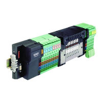
Burkert 8644 AirLINE Operating Instructions Manual (224 pages)
Remote Process Actuation Control System using Phoenix electronics modules
Brand:
Burkert
| Category:
Control Systems
| Size: 2 MB
Table of Contents
Deutsch
2
Table of Contents
2
Allgemeine Hinweise
6
Darstellungsmittel
7
Allgemeine Sicherheitshinweise
7
Schutz gegen Beschädigung durch Elektrostatische Aufladung
7
Sicherheitshinweise für das Ventil
8
Lieferumfang
9
Garantiebestimmungen
9
SYSTEMBESCHREIBUNG BÜRKERT-Airline-SYSTEM
10
System
10
Modulares Elektrisches/Pneumatisches Automatisierungssystem
11
Aufbau des Pneumatikblocks
13
Aufbau der Einspeisungen
14
Aufbau der Ventilscheiben
16
Ventilscheiben
16
Elektronik-Grundmodul 2Fach Typ ME02
18
Pneumatik-Grundmodul 2Fach Typ MP11
19
Ventile
20
Technische Daten des Pneumatikblocks
22
Aufbau des Systems
25
Feldbusknoten Profibus-Dp
26
Schnittstelle (Profibus)
28
24-V-Haupteinspeisung/24-V-Segmenteinspeisung
29
24-V-Modulversorgung
30
Logikversorgung (Potentialrangierer)
30
Analog-Versorgung (Potentialrangierer)
30
Derating der Logikversorgung und der Versorgung der Analog-Klemmen
31
Verlustleistung
32
Derating
32
Formel für die Berechnung der Verlustleistung der Elektronik
32
Schutzeinrichtungen
33
Anschlussmodule, Pneumatisch - Links Typ Me02
34
Varianten
34
Technische Daten
35
Leistungsmerkmale aus der Sicht des Gesamtsystems
35
Anschlussmodule, Pneumatisch - Mitte Typ Me02
36
Varianten
36
Technische Daten
37
Leistungsmerkmale aus der Sicht des Gesamtsystems
37
Anschlussmodule, Pneumatisch - Rechtstyp Me02
38
Varianten
38
Technische Daten
39
Leistungsmerkmale aus der Sicht des Gesamtsystems
39
Installation
41
Schritte zur Installation der Ventilinsel
41
Installationsanleitung
41
Entfernen der Transportsicherung
42
EINBAU des Airline-SYSTEMS
43
Fluidische Installation
44
Beschriftung der Anschlüsse
47
Elektrische Installation
48
Inbetriebnahme
50
Inbetriebnahme des Feldbusknoten Profibus-Dp
51
Der Profibus-Busknoten
51
9Poliger SUB-D-Stecker
52
DIP-Schalter
53
Diagnose-Leds Direkt an der Station
54
Klemmenbelegung der Einspeiseklemme
55
24-V-Segmenteinspeisung/24-V-Haupteinspeisung
56
24-V-Segmenteinspeisung
56
Massnahmen vor der Fluidischen Inbetriebnahme
57
Fluidische Inbetriebnahme
57
Konfiguration des Profibus-Dp
58
Konfiguration
59
Adressierung IM Prozessabbild (1)
60
Adressierung IM Prozessabbild (2)
60
Adressierung IM Prozessabbild (3)
61
Einstellungen in der Gsd-Datei
62
Auszug aus der Gsd-Datei
64
Diagnose und Fehlerbehebung am Profibus-Dp-Busknoten
67
Diagnose-Leds Direkt an der Station
67
Ermittlung der Fehlerursache
67
Ermittlung der Fehlerursache aus Fehlertyp und Fehlernummer
68
Diagnose der Profibusanschaltung
72
Fehlertyp und Fehlernummer
73
Störungsbeseitigung
74
English
76
General Notes
80
General Safety Notes
81
Protection from Damage by Electrostatic Charging
81
Symbols
81
Safety Notes for the Valve
82
Scope of Delivery
83
Warranty Conditions
83
DESCRIPTION of BÜRKERT Airline-SYSTEM
84
MODULAR ELECTRICAL/PNEUMATIC AUTOMATION SYSTEM TYPE 8644 Airline
85
Composition of the Pneumatic Block
87
Supply Modules
87
Valve Modules
90
Basic Electronic Module, 2-Fold Type ME02
92
Basic Pneumatic Module, 2-Fold Type MP11
93
Valves
94
Technical Data of the Pneumatic Block
96
Description of Overall System Bürkert - Phoenix
98
Composition of the System
99
Field Bus Node Profibus Dp
100
Technical Data of the Field Bus Node Profibus DP
101
Interface (Profibus)
102
24 V Main Power Supply / 24 V Segment Power Supply
103
24 V Module Power Supply
104
Logic Supply (Potential Shunter)
104
Analog Power Supply (Potential Shunter)
104
Derating of the Logic Power Supply and the Power Supply of the Analog Terminals
105
Power Loss
106
Derating
106
Formula for Calculation of the Power Loss of the Electronics
106
Protective Features
107
Connector Modules, Pneumatic, Left, Type Me02
108
Variants
108
Technical Data
109
Performance Characteristics Seen from the Overall System
109
Connector Modules, Pneumatic, Middle, Type Me02
110
Variants
110
Technical Data
111
Performance Characteristics Seen from the Overall System
111
Connector Modules, Pneumatic, Right, Type Me02
112
Variants
112
Technical Data
113
Performance Characteristics Seen from the Overall System
113
Installation
115
Instructions for Installation
115
Steps in the Installation of the Valve Island
115
Removal of the Transport Securing Device
116
Installation of the Airline System
117
Fluidic Installation
118
Electrical Installation
122
Commissioning
124
Commissioning of the Field Bus Node Profibus Dp
125
The Profibus Bus Node
125
9-Pole SUB-D Connector
126
DIP Switches
127
Diagnosis Leds Directly at the Station
128
Terminal Configuration of the Power Supply Terminal
129
24 V Segment Power Supply / 24 V Main Power Supply
130
24 V Segment Power Supply
130
Fluidic Commissioning
131
Measures to be Taken before Fluidic Commissioning
131
Configuration the Profibus-Dp
133
Configuration
133
Modules from the GSD File
133
Settings in the GSD File
136
Excerpt from the GSD File
138
Diagnosis and Error Elimination at the Profibus Dp Bus Node
141
Diagnosis Leds Directly at the Station
141
Determining the Cause of Error
141
Determining the Error from Error Type and Number
142
Diagnosis of the Profibus Connection
146
Error Type and Number
147
Français
150
Symboles de Precaution
155
Protection Contre Les Dommages Occasionnés Par Les Charges Électrostatiques
155
Consignes Generales
155
Consignes de Sécurité Relatives Aux Vannes
156
Couverture de Livraison
157
Prescriptions de Garantie
157
Systeme Modulaire D'automatisation Electrique/Pneumatique . Db
159
Architecture du Bloc Pneumatique
161
Architecture des Alimentations
162
Vannes
168
Caracteristiques Techniques du Bloc Pneumatique
171
Architecture du Systeme
173
Interface (Profibus)
176
Alimentation Logique (Structuration des Intensités)
178
Alimentation Analogique (Structuration des Intensités)
178
Analogiques
179
Puissance Dissipée
180
Dispositifs de Protection
181
Modules de Raccordement, Pneumatique - Gauche Type Me02
182
Variantes
182
Caractéristiques Techniques
183
Caractéristiques de Performance Considérées Au Niveau du Système Complet
183
Modules de Raccordement, Pneumatique - Central Type Me02
184
Variantes
184
Caractéristiques Techniques
185
Modules de Raccordement, Pneumatique - Droit Type Me02
186
Variantes
186
Caractéristiques Techniques
187
Installation
188
Instruction D'installation
189
Etapes D'installation de L'îlot de Vannes
189
Enlèvement de la Sécurité de Transport
190
Intégration du Système Airline
191
Installation Fluidique
192
Inscriptions de Repérage des Raccords
195
Installation Électrique
196
Bloc de Connexion Profibus
198
Témoins LED de Diagnostic Placés Directement Sur la Station
202
Alimentation Segmentée en 24V / Alimentation Principale en 24V
204
Alimentation Segmentée en 24V
204
Modules de Fichier GSD
207
Extrait du Fichier GSD
212
Diagnostic Et Levee des Erreurs Au Niveau du Coupleur de Bus Profibus-Dp
215
Témoins LED de Diagnostic Placés Directement Sur la Station
215
Détermination de la Cause D'erreur
215
Diagnostic de Branchement Profibus
220
Type Et Numéro D'erreur
221
Elimination des Anomalies
222
Advertisement
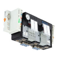
Burkert 8644 AirLINE Operating Instructions Manual (70 pages)
With I/O System 750 Wago, Remote Process Actuation Control System
Brand:
Burkert
| Category:
Control Systems
| Size: 2 MB
Table of Contents
Table of Contents
3
Operating Instructions
6
Symbols
6
Authorized Use
7
Restrictions
7
Explosion Protection Approval
7
Predictable Misuse
7
Basic Safety Instructions
8
General Information
9
Scope Of Supply
9
Contact Addresses
9
Warranty
9
Licenses
9
Information On The Internet
10
System Description
11
Application Area
11
Description Of The System
11
Structure Of The System
12
Characteristic Features And Advantages
13
Characteristic Features Of Airline
13
Advantages Of Airline
13
Diagram Of The Valve Block
14
Exploded Drawing
15
Exploded Drawing - Add-On Dimension 11 MM
15
Exploded Drawing - Add-On Dimension 16.5 MM
16
Technical Data
17
Operating Conditions
17
Technical Data Of The Entire System
17
Technical Data Of The Valve Block
18
Pneumatic Data Of The Connection Modules
20
Dimensioning of the Connection Modules
20
Performance Features from the Point of View of the Entire System
21
Electrical Data
22
Electronic Base Module ME02 / 2-Fold Monostable, ME02 / 2-Fold 2 X Monostable
22
Electronic Base Module ME02 / 8-Fold Monostable, ME02 / 8-Fold 2 X Monostable
23
Electronic Base Module ME02 / 2-Fold Bistable, ME02 / 8-Fold Bistable
24
Electronic Base Module ME03 / 2-Fold Monostable, ME03 / 2-Fold Bistable
25
Electronic Base Module ME03 / 3-Fold 10 MM Monostable, ME03 / 4-Fold Monostable
26
Structure and Function of the Modules
27
Connection Modules / Feeds
27
Valve Block
27
Valve Discs MK03
28
Connection Modules
30
Structure of the Connection Module
30
Connection Modules, Pneumatic - on Left Type ME02
32
Connection Modules, Pneumatic - in Middle Type ME02
33
Connection Modules, Pneumatic - on Right Type ME02
34
Connection Modules, Pneumatic - on Left Type ME03
35
Connection Modules, Pneumatic - in Middle Type ME03
36
Connection Modules, Pneumatic - on Right Type ME03
37
Electronic Base Module
38
General Description
38
Electronic Base Module ME02 / 2-Fold Monostable
40
Electronic Base Module ME02 / 2-Fold 2 X Monostable
41
Electronic Base Module ME02 / 8-Fold Monostable
42
Electronic Base Module ME02 / 8-Fold 2 X Monostable
43
Electronic Base Module ME02 / 2-Fold Bistable
44
Electronic Base Module ME02 / 8-Fold Bistable
45
Electronic Base Module ME03 / 2-Fold Monostable
46
Electronic Base Module ME03 / 2-Fold Bistable
47
Electronic Base Module ME03 / 3-Fold 10 MM Monostable
48
Electronic Base Module ME03 / 4-Fold Monostable
49
General Description
50
Pneumatic Base Module
50
Pneumatic Base Module with Integrated P Shut-Off
51
General Description
53
Valves
53
Installation
56
Safety Instructions
56
Removing The Valve Block From The Top-Hat Rail
57
Installing The Airline System (E.g. In The Control Cabinet)
58
Changing The Electrical Function Module
59
Fluid Installation
60
Pneumatic Connections - Feed
60
Removing the Plug-In Connections
61
Pneumatic Connections - Valve Discs
61
Electrical Installation
62
Maintenance, Troubleshooting
63
Safety Instructions
63
Troubleshooting
63
Maintenance Of Components
64
UL Handling
64
Start-Up
65
Electrical Start-Up
65
Selection of the Modules in the GSD File
66
Packaging and Transport
67
Disposal
68
Fluid Start-Up
65
Safety Instructions
65
Burkert 8644 AirLINE Operating Instructions Manual (73 pages)
Brand:
Burkert
| Category:
Measuring Instruments
| Size: 8 MB
Table of Contents
Table of Contents
3
1 Operating Instructions
6
Symbols
6
Definition of Terms
7
2 Intended Use
8
3 Basic Safety Instructions
9
4 General Notes
11
Contact Address
11
Warranty
11
Information Online
11
Standards and Directives
11
5 Product Description
12
Application Range
12
General Description
12
System Structure
13
Exploded View
15
Exploded View - Width Per Station 11Mm, REV.1
15
Exploded View - Width Per Station 11 MM, REV.2
16
Exploded View - Width Per Station 16 MM, REV.1
17
Location and Description of the Type Labels
18
Valve Island Type Label
18
UL Type Label
18
Valve Type Label
19
Information on Compatibility and Revision Status
20
Overview of Revision Statutes for the Different Widths Per Station
20
Information on Revision 2 (REV.2)
22
Distinguishing Features between REV.1 and REV.2
22
6 Technical Data
23
Operating Conditions
23
Technical Data of the Overall System
23
Technical Data of the Valve Block
25
Electrical Data
27
Performance Characteristics from the Perspective of the Overall System
27
Electrical Basic Module ME02 / 2-Fold Monostable, ME02 / 2-Fold 2 X Monostable
28
Electrical Basic Module ME02 / 8-Fold Monostable, ME02 / 8-Fold 2 X Monostable
29
Electronic Base Module ME02 / 2-Fold Bistable, ME02 / 8-Fold Bistable
30
Electronic Base Module ME03 / 2-Fold Monostable, ME03 / 2-Fold Bistable
31
Electronic Base Module ME03 / 3-Fold 10 MM Monostable, ME03 / 4-Fold Monostable
32
7 Structure and Function of the Modules
33
Valve Block
33
Electrical Connection Modules
34
Electronic Base Modules
35
Electronic Base Module ME02 / 2-Fold Monostable
37
Electronic Base Module ME02 / 2-Fold 2 X Monostable
38
Electronic Base Module ME02 / 8-Fold Monostable
39
Electronic Base Module ME02 / 8-Fold 2 X Monostable
40
Electronic Base Module ME02 / 2-Fold Bistable
41
Electronic Base Module ME02 / 8-Fold Bistable
42
Electronic Base Module ME03 / 2-Fold Monostable
43
Electronic Base Module ME03 / 2-Fold Bistable
44
Electronic Base Module ME03 / 3-Fold 10 MM Monostable
45
Electronic Base Module ME03 / 4-Fold Monostable
46
Pneumatic Connection Modules
47
Pneumatic Base Modules
49
Valves
50
Valves Type 6524 and Type 6525 for Valve Islands Width Per Station 11 MM
50
Valves Type 0460 for Valve Islands Width Per Station 11 MM
55
Valves Type 6526 and Type 6527 for Valve Islands Width Per Station 16 MM
56
Valves Type 0461 for Valve Islands Width Per Station 16 MM
58
8 Installation and Start-Up of the Valve Island in the Control Cabinet
59
Safety Instructions
59
Removing the Transport Lock from the Valve Block
60
Installation on Standard Rail
61
Fluidic Installation
62
Pneumatic Installation of the Connection Units
62
Pneumatic Installation of the Valve Units
63
Installation with Airline Quick (Only Valve Islands Width Per Station 11 MM)
64
Airline Quick in a Potentially Explosive Atmosphere
64
Installation of Airline Quick
65
Dimensions of the Flange Patterns for Airline Quick
66
Assignment of the Pneumatic Connections for Airline Quick
67
Electrical Installation
67
9 Maintenance, Troubleshooting
68
Safety Instructions
68
Troubleshooting
68
Maintenance of Components
69
UL Handling
69
10 Start-Up
70
Safety Instructions
70
Fluidic Start-Up
70
Electrical Start-Up
70
Selection of Modules in the GSD File
71
11 Accessories, Spare Parts
72
Accessories, Spare Parts For Width Per Station 11 MM
72
12 Packaging, Transport, Storage
73
Advertisement
Burkert 8644 AirLINE Operating Instructions Manual (68 pages)
With decentralized peripheral system ET200S (Siemens)
Brand:
Burkert
| Category:
Control Systems
| Size: 2 MB
Table of Contents
Operating Instructions
1
Table of Contents
3
1 Operating Instructions
6
Symbols
6
2 Authorized Use
7
Restrictions
7
Explosion Protection Approval
7
3 Basic Safety Instructions
8
4 General Information
9
Contact Addresses
9
Warranty
9
Licenses
9
Information On The Internet
9
5 System Description
10
Application Area
10
Description Of The System
10
Structure Of The System
11
Characteristic Features And Advantages
12
Characteristic Features Of Airline
12
Advantages Of Airline
12
Diagram Of The Valve Block
13
Exploded Drawing
14
Exploded Drawing - Add-On Dimension 11 MM
14
Exploded Drawing - Add-On Dimension 16.5 MM
15
6 Technical Data
16
Operating Conditions
16
Technical Data Of The Entire System
16
Technical Data Of The Valve Block
17
Pneumatic Data Of The Connection Modules
19
Dimensioning of the Connection Modules
19
Performance Features from the Point of View of the Entire System
20
Electrical Data
21
Electronic Base Module ME02, ME03 / 2-Fold Monostable
21
Electronic Base Module ME02, ME03 / 4-Fold Monostable
22
Electronic Base Module ME02, ME03 / 2-Fold Bistable
23
Electronic Base Module ME02 / 2-Fold 2 X Monostable
24
Electronic Base Module ME03 / 3-Fold 10 MM Monostable
25
7 Structure and Function of the Modules
26
Valve Block
26
Connection Modules / Feeds
26
Valve Discs MK03
27
Connection Modules
29
Structure of the Connection Module
29
Connection Modules, Pneumatic - on Left Type ME02
31
Connection Modules, Pneumatic - in Middle Type ME02
32
Connection Modules, Pneumatic - on Right Type ME02
33
Connection Modules, Pneumatic - on Left Type ME03
34
Connection Modules, Pneumatic - in Middle Type ME03
35
Connection Modules, Pneumatic - on Right Type ME03
36
Electronic Base Module
37
General Description
37
Electronic Base Module ME02 / 2-Fold Monostable
39
Electronic Base Module ME02 / 4-Fold Monostable
40
Electronic Base Module ME02 / 2-Fold Bistable
41
Electronic Base Module ME02 / 2-Fold 2 X Monostable
42
Electronic Base Module ME03 / 2-Fold Monostable
43
Electronic Base Module ME03 / 4-Fold Monostable
44
Electronic Base Module ME03 / 3-Fold 10 MM Monostable
45
Electronic Base Module ME03 / 2-Fold Bistable
46
Pneumatic Base Module
47
General Description
47
Pneumatic Base Module with Integrated P Shut-Off
48
Valves
50
General Description
50
8 Installation
53
Safety Instructions
53
Removing The Valve Block From The Top-Hat Rail
54
Installing The Airline System (E.g. In The Control Cabinet)
56
Changing The Function Module
56
Fluid Installation
57
Pneumatic Connections - Feed
58
Removing the Plug-In Connections
58
Pneumatic Connections - Valve Discs
59
Electrical Installation
60
9 Maintenance, Troubleshooting
61
Safety Instructions
61
Troubleshooting
61
Maintenance Of Components
62
UL Handling
62
10 Start-Up
63
10.1. Safety Instructions
63
10.2. Fluid Start-Up
63
10.3. Electrical Start-Up
63
10.3.1. Selection Of The Modules In The Gsd File
64
11 Packaging and Transport
65
12 Storage
66
13 Disposal
66
Burkert 8644 AirLINE Quick Start Manual (58 pages)
Brand:
Burkert
| Category:
Control Systems
| Size: 4 MB
Table of Contents
English
3
Table of Contents
3
Quickstart
4
Symbols
4
Intended Use
5
Foreseeable Misuse
5
General Safety Information
6
General Information
7
Contact Address
7
Warranty
7
Informations In The Internet
7
Application Area
8
System Description
8
Technical Data
9
Conformity
9
Standards
9
General Technical Data
9
Technical Data Of Valves
9
Structure And Installation
11
Safety Instructions
11
Structure
12
Assembly
13
Removing The Valve Block From The Standard Rail
16
Installation
17
Safety Instructions
17
Fluid Installation
17
Start-Up
19
Electrical Installation
19
Safety Instructions
19
Fluid Start-Up
19
Transport, Storage, Disposal
20
Electrical Start-Up
20
Deutsch
21
Darstellungsmittel
22
Der Quickstart
22
Bestimmungsgemässe Verwendung
23
Vorhersehbarer Fehlgebrauch
23
Grundlegende Sicherheitshinweise
24
Allgemeine Hinweise
25
Gewährleistung
25
Informationen IM Internet
25
Kontaktadresse
25
Beschreibung Des Systems
26
Einsatzbereich
26
Systembeschreibung
26
Allgemeine Technische Daten
27
Konformität
27
Normen
27
Technische Daten
27
Technische Daten Ventile
27
Aufbau Und Montage
29
Sicherheitshinweise
29
Aufbau
30
Montage
31
Entfernen Des Ventilblocks Von Der Normschiene
34
Fluidische Installation
35
Installation
35
Sicherheitshinweise
35
Elektrische Installation
37
Fluidische Inbetriebnahme
37
Inbetriebnahme
37
Sicherheitshinweise
37
Elektrische Inbetriebnahme
38
Transport, Lagerung, Verpackung
38
Français
39
Quickstart
40
Symboles
40
Mauvaise Utilisation Prévisible
41
Utilisation Conforme
41
Consignes De Sécurité Générales
42
Adresse
43
Garantie Légale
43
Indications Générales
43
Information Sur Internet
43
Description Du Système
44
Utilisation
44
Caractéristiques Techniques
45
Caractéristiques Techniques Générales
45
Caractéristiques Techniques Vannes
45
Conformité
45
Normes
45
Consignes De Sécurité
47
Structure Et Montage
47
Structure
48
Montage
49
Retrait Du Bloc De Vannes Du Rail Normalisé
52
Consignes De Sécurité
53
Installation
53
Installation Fluidique
53
Consignes De Sécurité
55
Installation Électrique
55
Mise En Service
55
Mise En Service Fluidique
55
Mise En Service Électrique
56
Transport, Stockage, Élimination
56
Burkert 8644 AirLINE Operating Instructions Manual (66 pages)
Brand:
Burkert
| Category:
Controller
| Size: 1 MB
Table of Contents
Table of Contents
5
General Notes
7
Symbols
8
General Safety Notes
8
Scope of Delivery
10
Warranty Conditions
10
Approvals
10
Assembly Note
10
Information of the Internet
10
Installation/Commissinoning
11
Installation Instructions
12
Illustration of the Valve Block
12
Removing the Valve Block from the Top-Hat Rail
13
Installation of the Airline System
14
Fluidic Installation
15
Labelling of the Connections
16
Elektrical Installation
17
Fluidic Commissioning
17
Electrical Commissioning
17
Electrical Installation
17
Maintenance and Troubleshooting
19
Troubleshooting
20
System Description
21
System Description
23
Valve Units
27
Connector Modules
30
Basic Electronic Module ME 02 / 8-Fold 2 X Monostable
45
Basic Electronic Module ME03 / 2-Fold Monostable
46
Basic Electronic Module ME03 / 4-Fold Monostable
51
Basic Electronic Module ME03 / 3-Fold 10 MM Monostable
53
Basic Electronic Module ME03 / 2-Fold Bistable
54
Basic Pneumatic Module
55
Basic Pneumatic Module with Integral Pressure Shut-Off
56
Valves
57
Limitations for Use in Zone 2
59
Burkert 8644 AirLINE Quick Start Manual (26 pages)
Modular Valve Island for Pneumatics
Brand:
Burkert
| Category:
Industrial Equipment
| Size: 3 MB
Table of Contents
Table of Contents
3
The Quickstart
4
Definition of Terms
4
Symbols Used
4
Intended Use
5
Basic Safety Instructions
5
Notes on Compatibility and Revision Levels
7
Overview of Revision Levels
7
Notes on Valve Islands Revision 2 (Only Applies to "WAGO" Valve Islands)
8
Distinguishing Features between Valve Islands REV.1 and REV.2
9
Distinguishing Features between Individual Valves REV.1 and REV.2
9
General Information
10
Contact Address
10
Warranty
10
Information on the Internet
10
Technical Data
10
Standards and Guidelines
10
General Technical Data
10
Connect Valves
12
Single Valves Width Per Station 11 MM
12
Double Valves Width Per Station 11 MM
12
Single Valves Width Per Station 16 MM
13
Removing the Valve Block from the Standard Rail
13
Installation of the Valve Island in the Control Cabinet
14
Safety Instructions
14
Installation on Standard Rail
15
Installation with Airline Quick
16
Installation
18
Fluidic Installation
18
10.2 Electrical Installation
21
Start-Up
21
Safety Instructions
21
Fluidic Start-Up
21
Electrical Start-Up
22
Maintenance
22
Spare Parts
22
Transport, Storage, Packaging
23
Burkert 8644 AirLINE Quick Start Manual (17 pages)
Brand:
Burkert
| Category:
Control Systems
| Size: 1 MB
Table of Contents
Table of Contents
3
1 Quickstart
4
Definition Of The Term "Device
4
Symbols
4
2 Intended Use
5
Restrictions
5
3 General Safety Information
5
4 General Information
6
Contact Address
6
Warranty
6
Informations In The Internet
6
5 Technical Data
7
Conformity
7
Standards
7
General Technical Data
7
6 Assembly
8
Safety Instructions
8
Assembly
9
Removing The Valve Block From The Standard Rail
12
7 Installation
13
Fluid Installation
13
Fluid Deinstallation
15
Electrical Installation
15
8 Start-Up
16
Safety Instructions
16
Fluid Start-Up
16
Electrical Start-Up
16
9 Maintenance
16
10 Transport, Storage, Disposal
16
Advertisement
Related Products
Burkert FreeLINE 8645
Burkert 8605 Series
Burkert 8696
Burkert 8626 Series
Burkert 8635
Burkert 8692
Burkert 8693
Burkert 8619 Series
Burkert 8623
Burkert 8696 REV.2
Burkert Categories
Control Unit
Controller
Measuring Instruments
Transmitter
Accessories
More Burkert Manuals
Login
Sign In
OR
Sign in with Facebook
Sign in with Google
Upload manual
Upload from disk
Upload from URL