Table of Contents
Advertisement
Available languages
Available languages
Quick Links
H-10242, H-10243,
H-10244
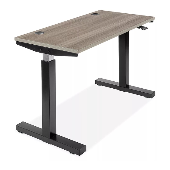
PNEUMATIC ADJUSTABLE
HEIGHT DESK
TOOLS NEEDED
Phillips Head
Drill
Screwdriver
NOTE: Count and inspect all pieces before
disposing of any carton or packing materials.
#
DESCRIPTION
1
Channel
2
Leg
3
Leg Screw, 6 x 12 mm
4
Side Frame
5
Tabletop
6
Wood Screw, 4.8 x 16 mm
7
Lever
8
Foot
9
Foot Screw, 8 x 65 mm
10
Glide
1.
Remove the two
plastic protectors
on the sides of the
channel (1).
(See Figure 1)
2. For easier assembly, place channel (1) on a raised
surface, such as a table. Insert metal rod located
inside of channel (1) into the mechanism opening
on the top of the leg (2). Repeat this step on the
opposite side. (See Figure 2)
PAGE 1 OF 9
1-800-295-5510
uline.com
Allen Wrench
(included)
QTY
1
2
16
2
1
18
1
2
8
4
Figure 1
1
Plastic Protector
Two Person Assembly
Recommended
ASSEMBLY
Figure 2
2
NOTE: If it is difficult to insert the rod into the
mechanism opening on the top of the leg:
• Align the arrow on the mechanism with
the screw. If metal rod will not insert into
mechanism opening on top of leg, press
center mechanism lever and rotate metal
rod to align arrow with screw on top of metal
rod. (See Figure 2)
• If still experiencing
difficulty inserting
the rod into the
mechanism opening,
slowly press down on
top of leg to turn
mechanism opening.
As opening turns,
push rod into opening
until it is inserted fully.
(See Figure 3)
Para Español, vea páginas 4-6.
Pour le français, consulter les pages 7-9.
Center Mechanism Lever
1
0323 IH-10242
Figure 3
Advertisement
Table of Contents

Related Manuals for U-Line H-10242


Summary of Contents for U-Line H-10242
- Page 1 Para Español, vea páginas 4-6. Pour le français, consulter les pages 7-9. H-10242, H-10243, 1-800-295-5510 H-10244 uline.com PNEUMATIC ADJUSTABLE HEIGHT DESK TOOLS NEEDED Two Person Assembly Phillips Head Drill Allen Wrench Recommended Screwdriver (included) ASSEMBLY NOTE: Count and inspect all pieces before...
- Page 2 ASSEMBLY CONTINUED 3. Insert six leg screws Figure 6 Figure 4 (3) into the sides and underside of the channel (1). Tighten using the Allen wrench. Repeat on opposite side. (See Figure 4) 4. Attach the side frames (4) to each end of channel using four leg screws (3).
-
Page 3: Operation
ASSEMBLY CONTINUED 11. Table is now fully assembled. With second person, Figure 9 carefully flip the table onto its feet. (See Figure 9) Lever OPERATION PNEUMATIC HEIGHT ADJUSTMENT Figure 10 • When raising/lowering table, use one hand to support the center of top and the other hand to lift lever. -
Page 4: Herramientas Necesarias
H-10242, H-10243, H-10244 800-295-5510 uline.mx ESCRITORIO DE ALTURA AJUSTABLE NEUMÁTICO HERRAMIENTAS NECESARIAS Se Recomienda Armar Desarmador Taladro Llave Allen Entre Dos Personas de Cruz (incluida) ENSAMBLE Diagrama 2 NOTA: Cuente e inspeccione todas las piezas Palanca Central para Mecanismo antes de desechar cualquier caja o material de empaque. - Page 5 CONTINUACIÓN DEL ENSAMBLE 3. Inserte seis tornillos Diagrama 6 Diagrama 4 para patas (3) en los lados y la parte inferior del canal (1). Apriete con la llave Allen. Repita este paso en el lado opuesto. (Vea Diagrama 4) 4. Fije los armazones laterales (4) a cada extremo del canal usando cuatro tornillos para patas (3).
-
Page 6: Solución De Problemas
CONTINUACIÓN DEL ENSAMBLE 11. La mesa ya está completamente ensamblada. Con Diagrama 9 ayuda de otra persona, voltee con cuidado la mesa y póngala de pie. (Vea Diagrama 9) Botón FUNCIONAMIENTO AJUSTE DE ALTURA NEUMÁTICO Diagrama 10 • Al levantar/bajar la mesa, use una mano para apoyar el centro de la cubierta y la otra mano para levantar la palanca. -
Page 7: Outils Requis
H-10242, H-10243, 1-800-295-5510 H-10244 uline.ca BUREAU PNEUMATIQUE À HAUTEUR RÉGLABLE OUTILS REQUIS Montage à deux personnes Tournevis Perceuse Clé Allen recommandé cruciforme (inclus) MONTAGE Figure 2 Levier central du mécanisme REMARQUE : Comptez et vérifiez toutes les pièces avant de jeter le matériel d'emballage ou le carton. - Page 8 MONTAGE SUITE 3. Insérez six vis de Figure 6 Figure 4 pied (3) dans les côtés et le dessous du profilé (1). Serrez à l'aide de la clé Allen. Répétez la procédure de l'autre côté. (Voir Figure 4) 4. Fixez les cadres latéraux (4) à chaque extrémité du profilé...
-
Page 9: Dépannage
MONTAGE SUITE 11. Le montage de la table est maintenant terminé. À Figure 9 deux, placez avec soin la table sur ses pieds. (Voir Figure 9) Levier FONCTIONNEMENT AJUSTEMENT PNEUMATIQUE DE LA HAUTEUR Figure 10 • En soulevant/abaissant la table, utilisez une main pour soutenir le centre de la surface et l'autre main pour soulever le levier.
Need help?
Do you have a question about the H-10242 and is the answer not in the manual?
Questions and answers