Table of Contents
Advertisement
Available languages
Available languages
Quick Links
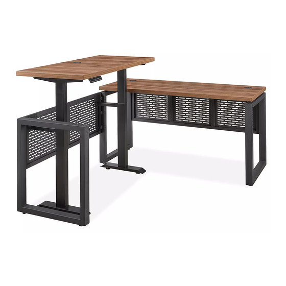
H-10357, H-10358
METRO COLLECTION –
ADJUSTABLE HEIGHT L-DESK
TOOLS NEEDED
Phillips
4 mm Allen Wrench
Screwdriver
(included)
A
B
Leg Frame
Modesty Panel
Connector x 4
Connector x 2
A
Leg Frame Connector x 2
E
M6 x 45 mm Bolt x 3
I
Flat Bracket x 2
L
M6 x 40 mm Bolt x 8
P
Foot Bracket (4 Holes) x 1
PAGE 1 OF 33
1-800-295-5510
uline.com
Drill
DESK HARDWARE
C
D
Adjustable
M6 x 55 mm
Glide x 4
Bolt x 4
L-DESK RETURN HARDWARE
B
Modesty Panel Connector x 1
F
M6 x 15 mm Bolt x 32
J
Leg Cap x 3
ADJUSTABLE HEIGHT BASE HARDWARE
M
M6 x 16 mm Bolt x 22
Q
Foot Bracket (3 Holes) x 1
Three Person Assembly
Recommended
E
F
M6 x 45 mm
M6 x 15 mm
Bolt x 6
Bolt x 20
C
Adjustable Glide x 2
G
Grommet Cap x 1
K
Hole Cap x 2
N
M6 x 10 mm Bolt x 12
R
Power Cord x 1
Para Español, vea páginas 12-22.
Pour le français, consulter les pages 23-33.
G
Grommet Cap x 2
D
M6 x 55 mm Bolt x 2
H
Z Connector x 3
O
ST5 x 16 mm Screw x 2
S
Cable
ST3.5 x 16 mm
Clip x 5
Screw x 6
0323 IH-10357
J
Leg Cap x 6
Advertisement
Table of Contents

Related Manuals for U-Line METRO H-10357


Summary of Contents for U-Line METRO H-10357
- Page 1 Para Español, vea páginas 12-22. Pour le français, consulter les pages 23-33. H-10357, H-10358 1-800-295-5510 uline.com METRO COLLECTION – ADJUSTABLE HEIGHT L-DESK TOOLS NEEDED Phillips 4 mm Allen Wrench Drill Three Person Assembly Screwdriver (included) Recommended DESK HARDWARE Leg Frame Modesty Panel Adjustable M6 x 55 mm...
- Page 2 DESK AND L-DESK RETURN PARTS DESK L-DESK RETURN FRAME DESK PARTS L-DESK RETURN FRAME PARTS DESCRIPTION QTY. DESCRIPTION QTY. Desktop Return Leg Frame Leg Frame Return Modesty Panel Modesty Panel ADJUSTABLE HEIGHT BASE PARTS ADJUSTABLE HEIGHT BASE ADJUSTABLE HEIGHT BASE PARTS DESCRIPTION QTY.
-
Page 3: Desk Assembly
DESK ASSEMBLY 3. Align two modesty panel connectors (B) with holes NOTE: Count and inspect all pieces before disposing of any carton or packing materials. in top of modesty panel (3). Attach using two M6 x 15 mm bolts (F) and tighten. (See Figure 3) NOTE: Assemble unit on a smooth, non-marring surface to prevent scratching. - Page 4 DESK ASSEMBLY CONTINUED 5. With second person, carefully lift the desktop (1) over Figure 5 assembled frame and align holes in the frame with holes in the leg frame connectors (A). Insert four M6 x 55 mm bolts (D) through leg frames into leg frame connectors and tighten.
- Page 5 L-DESK RETURN AND ADJUSTABLE HEIGHT BASE ASSEMBLY CONTINUED 3. Carefully flip over the base. Insert top support 5. Place base on top of return desktop with brackets brackets (8) into ends of center frame (9). Attach extending from lifting columns facing the grommet each bracket with two M6 x 10 mm bolts (N).
- Page 6 L-DESK RETURN AND ADJUSTABLE HEIGHT BASE ASSEMBLY CONTINUED Set assembled adjustable height base aside. L-desk 10. Align holes in the plates of the modesty panel support return frame will be assembled next. brackets (14) with holes in the top of return modesty panel (6).
- Page 7 L-DESK RETURN AND ADJUSTABLE HEIGHT BASE ASSEMBLY CONTINUED 12. Check bottom of return leg frame (5) to determine 14. Plug the programmable handset (7) and lifting whether to use foot bracket with three holes (Q) or with column cables into the control box. (See Figure 18) four holes (P).
- Page 8 L-DESK RETURN AND ADJUSTABLE HEIGHT BASE ASSEMBLY CONTINUED 16. Place cable clips (S) in desired location to neatly 18. Position the adjustable height return on right end of organize cables underneath the return desktop. the desk. Align the holes on the Z connectors (H) Cable clips can be attached using adhesive or with the holes inside the right leg (2).
-
Page 9: Operation
OPERATION CONTROLS Display Down Four Preset Setting Button Button Position Buttons Button Charger 2 3 4 1 2 3 4 M CAUTION! Ensure there are no obstacles in the desk's height adjustment path, and ensure the desk is not touching any walls. CAUTION! Ensure all cords are at the appropriate length to accommodate changes in height. -
Page 10: Troubleshooting
OPERATION CONTINUED LOCKING OPERATION • To lock the desk, press the "M" button to display " ". Hold the "M" button for 10 seconds until " " is displayed. • To unlock the desk, press and hold the "M" button for 10 seconds while " "... - Page 11 TROUBLESHOOTING CONTINUED OPERATING ISSUE RECOMMENDATIONS Desk does not go up or down, but handset Faulty height limits may be programmed and displays digits that are flashing. should be canceled. Press the "M" setting button to display " " on the handset. Press and hold the "M"...
- Page 12 H-10357, H-10358 800-295-5510 uline.mx COLECCIÓN METROPOLITANA – ESCRITORIO DE ALTURA AJUSTABLE EN L HERRAMIENTAS NECESARIAS Desarmador Llave Allen de 4 mm Se Recomienda Armar de Cruz (incluida) Taladro Entre Tres Personas TORNILLERÍA PARA ESCRITORIO 4 Conectores 2 Conectores 4 Tapas 4 Pernos 6 Pernos 20 Pernos...
- Page 13 PARTES DEL ESCRITORIO Y RETORNO PARA ESCRITORIO EN L ESCRITORIO ARMAZÓN DEL RETORNO PARA ESCRITORIO EN L PARTES DEL ARMAZÓN DEL RETORNO PARTES DEL ESCRITORIO DEL ESCRITORIO EN L DESCRIPCIÓN CANT. DESCRIPCIÓN CANT. Escritorio Armazón de la Pata para Retorno Armazón de la Pata Recato del Retorno Recato...
- Page 14 ENSAMBLE DEL ESCRITORIO NOTA: Cuente e inspeccione todas las piezas 3. Alinee los dos conectores para recato (B) con los antes de desechar cualquier caja o material orificios en la parte superior del recato (3). Fije de empaque. utilizando dos pernos M6 x 15 mm (F) y apriételos. (Vea Diagrama 3) NOTA: Ensamble la unidad sobre una superficie lisa que no deje marcas para evitar...
- Page 15 CONTINUACIÓN DEL ENSAMBLE DEL ESCRITORIO 5. Con ayuda de otra persona, levante con cuidado Diagrama 5 la cubierta (1) sobre el armazón ensamblado y alinee los orificios del armazón con los orificios en los conectores para armazón de las patas (A). Inserte cuatro pernos M6 x 15 mm (D) a través de los conectores y los armazones de las patas y apriételos.
- Page 16 CONTINUACIÓN DE ENSAMBLE DEL RETORNO DEL ESCRITORIO EN L Y BASE DE ALTURA AJUSTABLE 3. Voltee la base con cuidado. Inserte los brazos 5. Coloque la base encima de la cubierta del retorno de soporte superiores (8) en los extremos del con los soportes que se extienden de las columnas armazón central (9).
- Page 17 CONTINUACIÓN DE ENSAMBLE DEL RETORNO DEL ESCRITORIO EN L Y BASE DE ALTURA AJUSTABLE Deje la base de altura ajustable ensamblada a un 10. Alinee los orificios en la placa de los brazos de lado. El armazón del retorno para escritorio en L se soporte para recato (14) con los orificios en la ensamblará...
- Page 18 CONTINUACIÓN DE ENSAMBLE DEL RETORNO DEL ESCRITORIO EN L Y BASE DE ALTURA AJUSTABLE 12. Verifique la parte inferior del armazón de la pata 14. Conecte el control de programación (7) y los cables para retorno para determinar si debe utilizar el de las columnas de elevación a la caja de control.
- Page 19 CONTINUACIÓN DE ENSAMBLE DEL RETORNO DEL ESCRITORIO EN L Y BASE DE ALTURA AJUSTABLE 16. Coloque los clips para cableado (S) en la 18. Posicione el retorno de altura ajustable en el ubicación deseada para organizar los cables extremo derecho del escritorio. Alinee los orificios debajo de la cubierta del retorno.
-
Page 20: Ajuste De Altura
FUNCIONAMIENTO CONTROLES Cargador Pantalla Botón Botón Cuatro Botones de Posiciones Botón de Arriba Abajo Preprogramadas Ajuste 2 3 4 1 2 3 4 M ¡PRECAUCIÓN! Asegúrese de que no haya obstáculos en la trayectoria de la altura ajustable del escritorio y asegúrese de que no esté... -
Page 21: Solución De Problemas
CONTINUACIÓN DE FUNCIONAMIENTO BLOQUEO DE FUNCIONAMIENTO DEL ESCRITORIO • Para bloquear el escritorio, presione el botón de ajuste "M" para mostrar " ". Sostenga el botón "M" durante 10 segundos hasta que la pantalla muestre " ". • Para desbloquear el escritorio, presione y sostenga el botón "M" durante 10 segundo mientras la pantalla muestra "... - Page 22 CONTINUACIÓN DE SOLUCIÓN DE PROBLEMAS PROBLEMA DE FUNCIONAMIENTO RECOMENDACIONES El escritorio no sube ni baja, pero el control Los límites de altura podrían estar mal programados y se manual muestra dígitos que parpadean. deben cancelar. Presione el botón de ajuste "M" para mostrar "...
- Page 23 H-10357, H-10358 1-800-295-5510 uline.ca COLLECTION METRO – BUREAU EN L À HAUTEUR RÉGLABLE OUTILS REQUIS Tournevis Clé Allen de 4 mm Montage à trois personnes cruciforme (inclus) Perceuse recommandé MATÉRIEL D'INSTALLATION DU BUREAU Connecteur de Connecteur Patin de Boulon Boulon Boulon Capuchon pour Capuchon...
- Page 24 PIÈCES DU BUREAU ET DU RETOUR DE BUREAU EN L BUREAU CADRE DU RETOUR DE BUREAU EN L PIÈCES DU BUREAU PIÈCES DU CADRE DU RETOUR DE BUREAU EN L DESCRIPTION QTÉ DESCRIPTION QTÉ Surface de bureau Cadre de pied du retour Cadre de pied Panneau cache-jambes du retour...
- Page 25 MONTAGE DU BUREAU REMARQUE : Comptez et vérifiez toutes les 3. Alignez deux connecteurs de panneau pièces avant de jeter le matériel d'emballage cache-jambes (B) sur les trous situés sur la partie ou le carton. supérieure du panneau. Fixez-les avec deux boulons M6 x 15 mm (F), puis serrez-les.
- Page 26 MONTAGE DU BUREAU SUITE 5. À deux, déposez délicatement la surface de Figure 5 bureau (1) par-dessus le cadre assemblé, puis alignez les trous du cadre sur les trous des connecteurs de cadre de pied (A). Insérez quatre boulons M6 x 55 mm (D) à travers les cadres de pied jusque dans les connecteurs de cadre de pied, puis serrez-les.
- Page 27 MONTAGE DU RETOUR DE BUREAU EN L ET DE LA BASE À HAUTEUR RÉGLABLE SUITE 3. Retournez délicatement la base. Insérez les ferrures 5. Placez la base sur la surface du retour de bureau de support de la surface (8) dans les extrémités du avec les ferrures s'étendant des colonnes de levage cadre central (9).
- Page 28 MONTAGE DU RETOUR DE BUREAU EN L ET DE LA BASE À HAUTEUR RÉGLABLE SUITE Placez la base à hauteur réglable assemblée 10. Alignez les trous de la plaque des supports du de côté. Le cadre du retour de bureau en L-sera panneau cache-jambes (14) sur les trous situés sur assemblé...
- Page 29 MONTAGE DU RETOUR DE BUREAU EN L ET DE LA BASE À HAUTEUR RÉGLABLE SUITE 12. Vérifiez le bas du cadre de pied du retour (5) pour 14. Branchez le cordon d'alimentation (R) dans le déterminer s'il faut utiliser un support de pied à 3 boîtier de commande (10).
- Page 30 MONTAGE DU RETOUR DE BUREAU EN L ET DE LA BASE À HAUTEUR RÉGLABLE SUITE 15. À trois, faites soigneusement pivoter le retour 18. Positionnez le retour à hauteur réglable à l'extrémité assemblé vers le panneau cache-jambes et droite du bureau. Alignez les trous des connecteurs faites-le basculer sur les pieds.
-
Page 31: Réglage De La Hauteur
FONCTIONNEMENT COMMANDES Chargeur Affichage Touche Touche Quatre touches de Touche de haut position préréglée réglage 2 3 4 1 2 3 4 M MISE EN GARDE! Assurez-vous que le bureau ne touche aucun mur et qu'aucun obstacle n'entrave son mouvement. MISE EN GARDE! Assurez-vous que tous les cordons ont une longueur appropriée convenant au changement de hauteur. -
Page 32: Dépannage
FONCTIONNEMENT SUITE VERROUILLAGE DU BUREAU • Pour verrouiller le bureau, appuyez sur la touche « M » pour afficher « ». Maintenez enfoncée la touche « M » pendant 10 secondes jusqu'à ce que « » s'affiche. • Pour déverrouiller le bureau, appuyez et maintenez enfoncée la touche « M » pendant 10 secondes jusqu'à ce que « ... - Page 33 DÉPANNAGE SUITE PROBLÈME RECOMMANDATIONS Le bureau ne monte ni ne Des limites de hauteur erronées peuvent être programmées descend, mais le contrôleur et doivent être annulées. Appuyez sur la touche de réglage « M » manuel affiche des chiffres pour afficher « »...
Need help?
Do you have a question about the METRO H-10357 and is the answer not in the manual?
Questions and answers