Advertisement
Available languages
Available languages
Quick Links
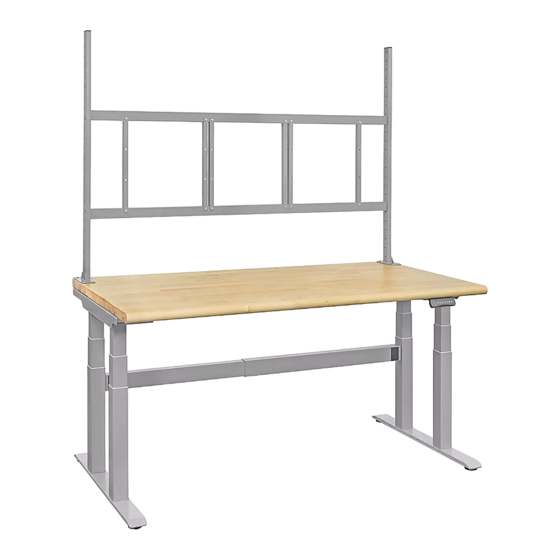
H-10268, H-10269
ADJUSTABLE HEIGHT
WORKSTATION
TOOLS NEEDED
Drill
1/4" Drill Bit
"A" Allen Head Bolt x 8
"F" Allen Head Bolt x 4
Foot x 2
Support Beam x 2
Rubber Pad x 8
PAGE 1 OF 42
Two Person Assembly
Recommended
Phillips Head
4 x 4 Allen Wrench
Drill Bit
5 x 5 Allen Wrench
(Included)
"B" Allen Head Bolt x 8
"C" Allen Head Bolt x 16
Handset Screw x 2
Front Lifting Column x 2
Rear Lifting Column x 2
Stringer x 1
Tabletop x 1
1-800-295-5510
uline.com
10mm Wrench
(Included)
PARTS
"D" Allen Head Bolt x 16
Stringer Cover x 2
Cable Tie x 6
Left Support Plate x 1
Upright x 2
Control Box x 1
2¾ Bolt x 8
Para Español, vea páginas 15-28.
Pour le français, consulter les pages 29-42.
"E" Phillips Head Screw x 14
Power Plug x 1
Right Support Plate x 1
Handset x 1
Upright Hardware Kit
Flange Nut x 8
Washer x 8
0323 IH-10268
Advertisement

Subscribe to Our Youtube Channel
Related Manuals for U-Line H-10268


Summary of Contents for U-Line H-10268
- Page 1 Para Español, vea páginas 15-28. Pour le français, consulter les pages 29-42. H-10268, H-10269 1-800-295-5510 uline.com ADJUSTABLE HEIGHT WORKSTATION Two Person Assembly Recommended TOOLS NEEDED Phillips Head Drill 1/4" Drill Bit 4 x 4 Allen Wrench 10mm Wrench Drill Bit...
- Page 2 ASSEMBLY Flip support plates upside down and adhere four 4. Place feet onto lifting columns, aligning holes rubber pads on corresponding holes of each support in feet to threaded inserts on bottom of lifting plate. (See Figure 1) columns. Attach using 16 "D" Allen head bolts and 4 x 4 Allen wrench.
- Page 3 ASSEMBLY CONTINUED NOTE: Support beams may need to expand for Using shaded circles as a guide, drill eight holes fully the holes to align. To expand, loosen eight through tabletop with 1/4" drill bit. (See Figure 7) pre-installed Allen head bolts. (See Figure 5a) NOTE: These holes are drilled to allow mounting Adjust length of support beams.
- Page 4 ASSEMBLY CONTINUED 9. Position handset at front edge of tabletop in desired 11. Place stringer between rear lifting columns, aligned position. Secure to tabletop using two handset screws with side mounting plates. Access hole in stringer and drill with Phillips head drill bit. (See Figure 9) should face the back side of the workstation.
- Page 5 ASSEMBLY CONTINUED UPRIGHT ASSEMBLY 14. Place stringer cover over holes on stringer. Tighten Allen head bolts on bottom of stringer to secure. 1. Carefully set table upright and recheck all nuts, (See Figures 14a-14b) bolts and screws for tightness. 2. Position upright on back corner of tabletop. The mounting plate should be positioned directly over the previously drilled holes.
- Page 6 OPTIONAL ACCESSORIES CUSTOMIZE WORKSTATION NOTE: The following products are optional accessories. Mounting hardware is included with each accessory. DESCRIPTION QTY. Bin Rail Shelf Bracket Shelf Pegboard Panel 16, 17 Louvered Panel Panel Mounting Bar Panel Bracket LED Shop Light Light Bracket Light Steel Beam ▲...
- Page 7 OPTIONAL ACCESSORIES CONTINUED 3. Place shelf on brackets. Install to brackets with 3. Install panels (pegboard and/or louvered) to the four 5/8" bolts and flange nuts. (See Figure 20) mounting bars. Align holes on the top and bottom of the panel with the holes in the bar. Secure using four 1⁄"...
- Page 8 OPTIONAL ACCESSORIES CONTINUED LIGHT KIT ASSEMBLY 5. Attach hanging chains to LED shop light and mount to "S" hooks. (See Figure 28) Line up light brackets with uprights at desired height. Figure 28 2. Secure to uprights with four 2" bolts and flange nuts. (See Figure 25) Flange SHELF DIVIDER ASSEMBLY...
- Page 9 OPTIONAL ACCESSORIES CONTINUED TABLETOP POWER STRIP ASSEMBLY ATTACHING MONITOR NOTE: Ensure monitor has a VESA hole pattern of 1. Choose desired location for power strip. Place two 100 x 100 mm or 75 x 75 mm. (See Figure 33) supplied mounting clips roughly 32" apart (clip side up).
- Page 10 OPTIONAL ACCESSORIES CONTINUED CABLE MANAGEMENT 2. Align hole on the opposite end of fan mounting bracket to the hole on the crescent fan bracket. 1. To remove covers, use a Phillips screwdriver to remove Attach using M12 x 20 mm hex bolt, M12 washer, the two screws securing covers to the monitor arm.
- Page 11 OPTIONAL ACCESSORIES CONTINUED ATTACHING KEYBOARD TRAY ADJUSTING TENSION Keyboard tray mount includes two built-in 1. Attach keyboard tray to gas spring arm using four counterweight systems for free-range motion. Arm in M4 Phillips head bolts and four M4 lock nuts with a mount may need to be adjusted to allow keyboard Phillips screwdriver and 7 mm wrench.
- Page 12 OPTIONAL ACCESSORIES CONTINUED CABLE MANAGEMENT Figure 44 Remove bottom cover by pulling down until it separates from arm. This allows user to slide cable through bottom cover and continue through gas spring arm cover. Once complete, strap bottom cover back onto bottom arm, covering cables. (See Figure 44) Bottom Bottom...
- Page 13 OPERATION CONTINUED COLLISION PREVENTION SENSITIVITY WORKSTATION DUTY CYCLE ADJUSTMENT • To protect the motor from overheating, the height can only adjust consistently for two minutes. Press and hold button for five seconds at the • If error code shows on display panel, same time to switch the sensitivity.
- Page 14 MAINTENANCE • Power supply: AC100V-240V, 50/60Hz • Slight noise caused by V-ribbed belt of brake system will not have any effect on use of equipment. • Service environment: 32˚-104˚F • Do not use corrosive or abrasive materials to • Unplug power plug before cleaning. Wipe dust on clean equipment.
- Page 15 H-10268, H-10269 800-295-5510 uline.mx ESTACIÓN DE TRABAJO DE ALTURA AJUSTABLE Se Recomienda Armar HERRAMIENTAS NECESARIAS Entre Dos Personas Broca de Cruz Taladro Broca de 1/4" Llave Allen de 4 x 4 Llave de 10mm Llave Allen de 5 x 5...
- Page 16 ENSAMBLE Pegue cuatro protectores de goma al reverso de 4. Coloque las patas en las columnas de elevación cada una de las placas de soporte en los orificios alineando los orificios de las patas a los insertos correspondientes. (Vea Diagrama 1) roscados de la parte inferior de las columnas de elevación.
- Page 17 CONTINUACIÓN DEL ENSAMBLE NOTA: Es posible que las vigas de soporte Usando los círculos sombreados como guía, perfore tengan que expandirse para que los orificios ocho orificios a través de la cubierta con una broca de 1/4". (Vea Diagrama 7) se alineen.
- Page 18 CONTINUACIÓN DEL ENSAMBLE 9. Coloque el control manual en el borde frontal de 11. Coloque el larguero entre las columnas de la cubierta en la posición deseada. Asegúrelo a la elevación posteriores alineado con las placas cubierta utilizando dos tornillos para control manual de instalación laterales.
- Page 19 CONTINUACIÓN DEL ENSAMBLE ENSAMBLE DE POSTES 14. Coloque la cubierta sobre los orificios del larguero. Apriete los pernos de cabeza Allen de la parte 1. Coloque con cuidado la mesa de forma vertical y inferior del larguero para asegurarlo. revise que todos los tornillos, pernos y tuercas estén (Vea Diagramas 14a-14b) apretados.
- Page 20 ACCESORIOS OPCIONALES PERSONALICE SU ESTACIÓN DE TRABAJO NOTA: Los siguientes productos son accesorios opcionales. Se incluye la tornillería de instalación con cada accesorio. DESCRIPCIÓN CANT. Riel para Gavetas Soporte para Repisa Repisa Tablero Perforado 16, 17 Panel de Rejillas Barra para Instalar el Panel Soporte de Panel Lámpara LED para Taller Soporte para Lámpara...
- Page 21 CONTINUACIÓN DE ACCESORIOS OPCIONALES 3. Coloque la repisa sobre los soportes. Instale en los 3. Instale los paneles (tablero perforado y/o de rejillas) soportes con cuatro pernos de 5/8" y tuercas con a las barras de instalación (6). Alinee los orificios de reborde.
- Page 22 CONTINUACIÓN DE ACCESORIOS OPCIONALES ENSAMBLE DEL KIT DE LÁMPARA 5. Acople las cadenas colgantes a la lámpara LED para taller e instale los ganchos en "S". 1. Alinee los soportes de lámpara con los postes a la (Vea Diagrama 28) altura deseada.
- Page 23 CONTINUACIÓN DE ACCESORIOS OPCIONALES ENSAMBLE DEL MULTICONTACTO DE FIJAR EL MONITOR MOSTRADOR NOTA: Asegúrese de que el monitor tenga el patrón de orificios VESA de 100 x 100 mm o Elija la ubicación deseada para el multicontacto. 75 x 75 mm. (Vea Diagrama 33) Coloque los dos clips de instalación suministrados con una separación aproximada de 32"...
- Page 24 CONTINUACIÓN DE ACCESORIOS OPCIONALES MANEJO DEL CABLEADO 2. Alinee el orificio del extremo opuesto del soporte de instalación del ventilador con el orificio del soporte Para retirar las cubiertas, use un desarmador de cruz semicircular para ventilador. Fije utilizando el perno para quitar los dos tornillos que las aseguran al brazo M12 x 20 mm, la rondana M12, la rondana de para monitor.
- Page 25 CONTINUACIÓN DE ACCESORIOS OPCIONALES FIJAR LA BANDEJA PARA TECLADO AJUSTAR LA TENSIÓN El soporte de la repisa para teclado incluye Fije la bandeja para teclado al brazo de pistón dos sistemas de contrapeso integrados para de gas usando cuatro pernos de cruz M4 y cuatro movimiento libre.
- Page 26 CONTINUACIÓN DE ACCESORIOS OPCIONALES MANEJO DEL CABLEADO Diagrama 44 Retire la cubierta inferior jalándola hacia abajo hasta separarla del brazo. Esto permite al usuario deslizar el cable a través de la cubierta inferior y continuar a través de la cubierta del brazo del pistón de gas.
- Page 27 CONTINUACIÓN DE FUNCIONAMIENTO AJUSTE DE SENSIBILIDAD DE PREVENCIÓN CICLO DE TRABAJO DE LA MESA DE COLISIÓN • Para evitar el sobrecalentamiento del motor, la altura sólo puede ajustarse de forma constante Presione y sostenga el botón durante cinco durante dos minutos. segundos a la misma vez para cambiar la sensibilidad.
- Page 28 MANTENIMIENTO • Suministro de energía: AC100V-240V, 50/60Hz • Un ruido leve causado por la correa acanalada en V del sistema de frenos no tendrá ningún efecto en • Ambiente de Servicio: 0˚-40˚C (32˚-104˚F) el uso del equipo. • Desconecte el enchufe de alimentación antes de •...
- Page 29 H-10268, H-10269 1-800-295-5510 uline.ca POSTE DE TRAVAIL À HAUTEUR RÉGLABLE Montage à deux personnes recommandé OUTILS REQUIS Embout de Perceuse Mèche de Clé Allen de 4 x 4 Clé de 10 mm perceuse perceuse de Clé Allen de 5 x 5...
- Page 30 MONTAGE Retournez les plaques de support à l'envers et appliquez 4. Placez les pieds sur les colonnes de levage, en sur les trous correspondants quatre coussinets en alignant les trous dans les pieds sur les douilles filetées caoutchouc pour chacune des plaques. (Voir Figure 1) au bas des colonnes de levage.
- Page 31 MONTAGE SUITE REMARQUE : Il se peut que les barres de En utilisant les cercles ombragés comme guide, support doivent être élargies pour que les trous percez huit trous à travers la surface de table avec une mèche de 1/4 po. (Voir Figure 7) soient alignés.
- Page 32 MONTAGE SUITE 9. Placez le contrôleur manuel sur le bord avant de la 11. Placez le longeron entre les colonnes de levage surface de table dans la position souhaitée. Fixez le arrière en l'alignant avec les plaques de montage contrôleur manuel sur la surface de table à l'aide latérales.
- Page 33 MONTAGE SUITE MONTAGE DU MONTANT 14. Placez le cache pour longeron sur les trous du longeron. Serrez les boulons Allen sur la partie inférieure du Placez avec soin la table à l'endroit et vérifiez que longeron pour le fixer. (Voir Figures 14a et 14b) tous les boulons, écrous et vis sont bien serrés.
- Page 34 ACCESSOIRES OPTIONNELS PERSONNALISEZ VOTRE POSTE DE TRAVAIL REMARQUE : Les articles suivants sont des accessoires optionnels. Le matériel de fixation est compris avec chaque accessoire. DESCRIPTION QTÉ Rail à bacs Support de tablette Tablette Panneau perforé 16, 17 Panneau à fentes Barre de fixation pour panneau Support de panneau Éclairage d'atelier à...
- Page 35 ACCESSOIRES OPTIONNELS SUITE 3. Placez la tablette sur les supports. Fixez-la aux 3. Installez les panneaux (perforés et/ou à fentes) sur supports à l'aide de quatre boulons de 5/8 po les barres de fixation. Alignez les trous en haut et en et d'écrous à...
- Page 36 ACCESSOIRES OPTIONNELS SUITE MONTAGE DE L ' ÉCLAIRAGE 5. Accrochez les chaînes d'éclairage d'atelier à DEL et fixez-les sur les crochets en « S ». (Voir Figure 28) 1. Alignez les supports d'éclairage sur les montants à la hauteur voulue. Figure 28 2.
- Page 37 ACCESSOIRES OPTIONNELS SUITE INSTALLATION DU MONITEUR MONTAGE DE LA BARRE MULTIPRISE DE TABLE REMARQUE : Assurez-vous que le moniteur 1. Choisissez l'emplacement voulu pour la barre possède une configuration de trous VESA de multiprise. Placez les deux pinces de fixation 100 x 100 mm ou de 75 x 75 mm. (Voir Figure 33) fournies à...
- Page 38 ACCESSOIRES OPTIONNELS SUITE GESTION DES CÂBLES 2. Alignez le trou à l'extrémité opposée du support de fixation pour ventilateur sur le trou du support de Si vous souhaitez retirer les caches, utilisez un cadre du ventilateur. Fixez le tout à l'aide du boulon tournevis cruciforme pour extraire les deux vis hexagonal M12 x 20 mm, de la rondelle M12, de la maintenant les caches au bras de moniteur.
- Page 39 ACCESSOIRES OPTIONNELS SUITE FIXATION DU PLATEAU À CLAVIER RÉGLAGE DE LA TENSION Le support du plateau à clavier comprend deux Fixez le plateau à clavier au bras avec vérin à gaz systèmes de contrepoids intégrés pour une à l'aide de quatre boulons à tête cruciforme M4 amplitude maximale de mouvement.
- Page 40 ACCESSOIRES OPTIONNELS SUITE GESTION DES CÂBLES Figure 44 Retirez le cache inférieur en le tirant vers le bas jusqu'à ce qu'il se sépare du bras. Cela permet à l'utilisateur de faire glisser le câble à travers le cache inférieur et de continuer à travers le couvercle du bras avec vérin à...
- Page 41 FONCTIONNEMENT SUITE RÉGLAGE DE LA SENSIBILITÉ POUR LA CYCLE D'UTILISATION DU POSTE PRÉVENTION DES COLLISIONS DE TRAVAIL • Pour protéger le moteur de la surchauffe, le réglage Appuyez sur la touche et maintenez-la de la hauteur ne peut être utilisé que pendant une enfoncée pendant cinq secondes simultanément période continue de 2 minutes.
- Page 42 ENTRETIEN • Alimentation électrique : CA, 100 V à 240 V, 50/60 Hz • Le léger bruit causé par la courroie à nervures en V du système de freinage n'a aucun effet sur • Environnement de fonctionnement : 32˚ à 104 ˚F l'utilisation de l'équipement.
Need help?
Do you have a question about the H-10268 and is the answer not in the manual?
Questions and answers