
Related Manuals for Winmate IBDRW100-EL


Summary of Contents for Winmate IBDRW100-EL
- Page 1 Preface DIN Rail Box PC IBDRW100-EL Intel® Elkhart Lake Celeron® N6210 1.2GHz, up to 2.6 GHz Intel® Elkhart Lake ATOM® x6425E 2.0GHz, up to 3.0 GHz User Manual Version 1.1 Document Part No. 91711110101Z...
-
Page 2: Table Of Contents
Contents Preface ............................3 About This User Manual ........................ 6 Chapter 1: Introduction ......................... 7 1.1 Product Overview ........................7 1.2 Product Features ........................7 1.3 Accessories ..........................7 1.4 Chassis Dimensions ........................8 1.5 Description of Parts ........................9 Chapter 2: Hardware Installation .................... -
Page 3: Preface
Preface Preface Copyright Notice No part of this document may be reproduced, copied, translated, or transmitted in any form or by any means, electronic or mechanical, for any purpose, without the prior written permission of the original manufacturer. Trademark Acknowledgement Brand and product names are trademarks or registered trademarks of their respective owners. - Page 4 and operation of any of our products. Advisory Conventions Four types of advisories are used throughout the user manual to provide helpful information or to alert you to the potential for hardware damage or personal injury. These are Notes, Important, Cautions, and Warnings.
- Page 5 Preface Safety Precautions For your safety carefully read all the safety instructions before using the device. Keep this user manual for future reference. • Replacement of a battery with an incorrect type that can defeat a safeguard • Disposal of a battery into fire or a hot oven, or mechanically crushing or cutting of a battery, that can result in an explosion •...
-
Page 6: About This User Manual
This User Manual provides information about using the IBDRW100-EL Series DIN Rail Box PC. This User Manual applies to the IBDRW100-EL Series DIN Rail Box PC - IBDRW100-EL. The documentation set for the IBDRW100-EL Series DIN Rail Box PC provides information for specific user needs, and includes: •... -
Page 7: Chapter 1: Introduction
With a compact size and small form factor as well as front accessible I/O port. The IBDRW100-EL Series is very convenient for wiring and DIN-rail installation in the control cabinet. The wide operation temperature and Industrial serial port design makes this unit a perfect communication even in harsh and critical location. -
Page 8: Chassis Dimensions
1.4 Chassis Dimensions Unit: mm... -
Page 9: Description Of Parts
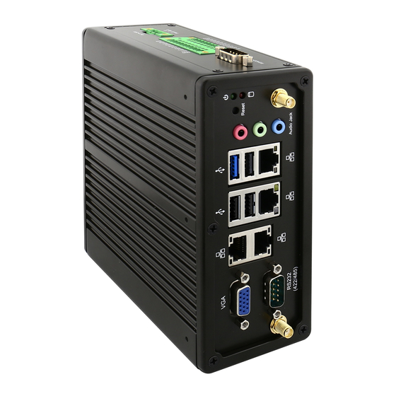
Chapter 1: Introduction 1.5 Description of Parts Front 1. VGA 2. COM1 RS232 default (RS422/485 selected by BIOS setting) 3. LAN x 2 4. LAN x 2 5. USB 2.0 x 1 6. USB 3.2 Gen2x1 x 3 7. Audio Jack 8. -
Page 10: Chapter 2: Hardware Installation
STDA_SSTX+ 2.1.2 RJ-45 for LAN Connector The IBDRW100-EL has four LAN connectors located on the front. Ethernet ports provide a standard RJ45 jack connector with LED indicators on the front side to show its Active/ Link status and Speed status. -
Page 11: Serial Port Rs-232/422/485 Connector
Pin assignment and signal names of isolated RS-422/485 connector Pin № RS422 RS485 DATA- DATA+ 2.1.7 Audio Jack The IBDRW100-EL have has three stereo audio ports with audio jack connectors: Mic-in, Line- out, Line-in. Pin assignment and signal names of audio jack Color Signal Name BLUE Line-in... -
Page 12: Dido Connector
DINT3 GPIO57_OUT1 2.1.9 DC Power 3pin Terminal Block The DC power source input of the IBDRW100-EL is a 3-pin terminal block connector that supports 9-36V DC power input. Pin assignment and signal names of DC power 3pin terminal block Minimum Voltage 9V... -
Page 13: Configuring Com2 Settings By Jumpers
Chapter 2: Hardware Installation 2.2 Configuring COM2 Settings by Jumpers Serial Port COM2 can be configured for RS-422 or RS-485 by jumpers. Jumpers are located on the motherboard. You need to open the housing in order to access the jumpers. Caution It is recommended to use factory jumper settings. -
Page 14: Chapter 3: Initial Setup
Chapter 3: Initial Setup 3.1 DIN Rail Mounting Setup Please follow these steps to mount the IBDRW hook kit on a DIN rail Screw the provided DIN-rail Kit on the rear side of the box as the diagram shown below. Please make sure the stiff metal handle part is located on the top. -
Page 15: Chapter 4: Insyde Bios Setup
Power On Self-Test (POST): “Press DEL to run SETUP” Note: BIOS version update may be published after the manual is released. Please visit Winmate Download Center to check the latest version of BIOS. User may need to run BIOS setup... -
Page 16: Bios Menu
4.2 BIOS Menu 4.2.1 Main Immediately after the [DEL] key is pressed during startup to show the main BIOS setup menu: BIOS Setting Description Setting Options Effect Select the current default Adjustment of the Set the default Language language by the language. -
Page 17: Advanced
Chapter 4: Insyde BIOS Setup 4.2.2 Advanced BIOS Setting Description Setting Option Effect Configures Trusted Opens CPU Configuration Enter Computing parameters submenu Configures Power & Opens Power& Performance Enter Performance parameters submenu Configures System Agent Opens System Agent Configuration Enter Configuration parameters submenu Configures PCH-OI... - Page 18 4.2.2.1 CPU Configuration BIOS Setting Description Setting Option Effect When enabled, a VMM Intel (VMX) Enable or disable Intel can utilize the additional Virtualization Virtualization Enable/Disable hardware capabilities Technology Technology. provided by Vander pool Technology. Active Number of core to Select number of core to Processor enable in each...
- Page 19 Chapter 4: Insyde BIOS Setup 4.2.2.2 CPU Power Management Configuration BIOS Setting Description Setting Option Effect -Max non-turbo Select the performance Boot Configure Boot performance state that the BIOS will Performance Performance Mode -Max battery set starting from reset Mode parameters -Turbo vector...
- Page 20 states when it is not 100% utilized Custom P-state Configure Custom P- Enter Enters sub-menu Table state Table parameters Set the number of -Number of P- Select the number of [Number] custom P-states. At least states custom P-states. 2 states must be present 4.2.2.3 System Agent Configuration BIOS Setting Description...
- Page 21 Chapter 4: Insyde BIOS Setup 4.2.2.4 PCH-IO Configuration BIOS Setting Description Setting Option Effect PCI Express clock PCI Express gating enable/disable Enter Opens sub-menu Configuration for each root port. SATA And RST Enable/ Disable SATA Enter Opens sub-menu Configuration device Selectively enable/ disable the corresponding USB...
- Page 23 Chapter 4: Insyde BIOS Setup...
- Page 25 Chapter 4: Insyde BIOS Setup...
- Page 26 4.2.2.5 ME Firmware Configuration...
- Page 27 Chapter 4: Insyde BIOS Setup 4.2.2.5 S10 F81968 Configuration...
- Page 29 Chapter 4: Insyde BIOS Setup 4.2.2.6 Hardware Monitor...
-
Page 30: Security
4.2.4 Security BIOS Setting Description Setting Option Effect TrEE Protocol Choose TrEE Protocol TrEE Protovol Version Version Version: 1.0 or 1.1 When hidden don’t TPM Availability Available TPM Availability configuration Hidden exposes TPM to 0 Select one of the TPM Operation TPM Operation supported operation configuration... -
Page 31: Power
Chapter 4: Insyde BIOS Setup 4.2.5 Power BIOS Setting Description Setting Option Effect Enable/ Disable Disabled ACPI S3 ACPI S3 configuration ACPI S1/S3 Sleep Enabled state Disabled Auto Wake on S5, Auto Wake on S5 By Every Day by Day or Month or Auto Wake on S5 configuration By Every... -
Page 32: Boot
4.2.6 Boot BIOS Setting Description Setting Option Effect Select boot type to Dual UEFI Boot Boot Type Boot Type configuration type, Legacy type or Type UEFI type Allows InsydeH20 to skip certain tests while Enabled booting. This will Quick Boot Quick Boot configuration Disabled decrease the time... -
Page 33: Exit
Chapter 4: Insyde BIOS Setup 4.2.7 Exit... -
Page 34: Using Recovery Wizard To Restore The System
Plug-in the AC adapter to Box PC. Make sure the Box PC stays plugged in to power source during the recovery process. • Turn on the IBDRW100-EL DIN-Rail Box PC, and when the boot screen shows up, press the F6 to initiate the Recovery Wizard. •... -
Page 35: Chapter 5: Driver Installation
Chapter 5: Driver Installation Chapter 5: Driver Installation Driver installation procedure described in this user manual applies to Windows 10 IoT Enterprise operating system. 5.1 Chipset Driver Installation Follow the instructions below to complete the installation. You will quickly complete the installation. Step 1 Open the Driver CD (included in the package) and select Chipset driver. - Page 36 Step 3 Select Accept to agree with the terms of license agreement. Step 4 Check the ReadMe file information, select Install to continue.
- Page 37 Chapter 5: Driver Installation Step 5 Wait for the driver to be installed. When installation completed, select Restart Now to restart your computer.
-
Page 38: Graphics Driver Installation
5.2 Graphics Driver Installation IBDRW100-EL DIN-Rail Box PC is equipped with Intel SoC Integrated Device. Follow the instructions below to complete the installation. You will quickly complete the installation. Step 1 Open the Driver CD (included in the package) and select Graphic driver. - Page 39 Chapter 5: Driver Installation Step 3 Select Accept to agree with the terms of license agreement.
- Page 40 Step 4 Check the ReadMe file information, select Next to continue. Step 5 Wait for the driver to be installed.
- Page 41 Chapter 5: Driver Installation Step 6 Select Next to continue. Step 6 After installation is completed, select “Yes, I want to restart this computer now”, and click Finish.
-
Page 42: Management Engine (Me) Installation
5.3 Management Engine (ME) Installation Follow the instructions below to complete the Management Engine (ME) . Driver installation. Step 1 Open the Driver CD (included in the package) and select ME driver. Step 2 Select Next to start the installation. - Page 43 Chapter 5: Driver Installation Step 3 Select Next to agree with the terms of license agreement. Step 4 Wait for the driver to be installed.
- Page 44 Step 5 When installation completed, select Finish complete installation.
-
Page 45: Sst Driver Installation
Chapter 5: Driver Installation 5.4 SST Driver Installation Follow the instructions below to complete the SST Driver installation. Step 1 Update Drivers > Browse “My computer” for driver software > Next Step 2 Wait for driver installation to complete. - Page 46 When the line-out volume is turned off, HDMI will also have no audio output. If you will not use the line-in function, please keep the Winmate default setting. When you need to use the line-in function, please follow the steps below to turn on the sync output.
- Page 47 Chapter 5: Driver Installation STEP 2 :...
-
Page 48: Audio Driver Installation
5.5 Audio Driver Installation Follow the instructions below to complete the Audio Driver installation. Step 1 Open the Driver CD (included in the package) and select Audio driver. Step 2 Select Next to continue. - Page 49 Chapter 5: Driver Installation Step 3 When installation completed, select Finish complete installation.
- Page 50 5.6 Ethernet Driver Installation Follow the instructions below to complete the Ethernet Driver installation. Step 1 Open the Driver CD (included in the package) and select LAN driver. Step 2 When compression is complete, select Next.
- Page 51 Chapter 5: Driver Installation Step 3 Read the license agreement, and then select Next. Step 4 System displays the installed packages, select Next.
- Page 52 Step 5 Confirm the installation, select Install to start the installation. Step 6 When installation is completed, select Finish to close the window.
- Page 53 Chapter 5: Driver Installation 5.7 Watchdog Driver Installation For more details about Winmate Watchdog, please download Watchdog Guide from Winmate Downloads Center: Follow instructions below to install Watchdogdriver. Step 1 Type “cmd” in the run box then the cmd.exe will appear in programs.
- Page 54 Step 5 Open the Driver CD (included in the package) and select Watchdog AP.
- Page 55 Chapter 5: Driver Installation Step 6 Select Next. Step 7 The installed storage location is displayed, select Next to continue.
- Page 56 Step 8 Select Next to start the installation. Step 9 When installation is completed, select Finish to close the window.
- Page 57 Chapter 5: Driver Installation 5.8 FTDI Driver Installation Follow instructions below to install FTDI driver. Step 1 Open the Driver CD (included in the package) and select FTDI driver. Step 2 Right click on "ftdibus" Step 3 Select Install Step 4 Right click on "ftdiports" Step 5 Select Install...
- Page 58 5.9 Serial IO Driver Installation Follow instructions below to install Serial IO driver. Step 1 Open the Driver CD (included in the package) and select Serial IO driver. Step 2 Right click on " iaLPSS2_GPIO2_EHL " Step 3 Select Install Step 4 Right click on "...
- Page 59 Chapter 5: Driver Installation 5.10 Digital IO Driver Installation Follow instructions below to install Digital IO driver. Step 1 Open the Driver CD (included in the package) and select Winmate_PPC_Digital_IO_SDK_V2.4(IEDR)(2) driver. Step 2 select 5.1.0.2...
- Page 60 Step 3 select WMDIO Driver for Win7_64bit Step 4 chick File on the top left...
- Page 61 Chapter 5: Driver Installation Step 5 Select Open Windows PowerShell as administrator...
- Page 62 Step 6 Select Install Step 7 Back to Winmate_PPC_Digital_IO_SDK_V2.4(IEDR)(2) and select SampleCode...
- Page 63 Chapter 5: Driver Installation Step 8 Select WMDIOAPP...
- Page 64 Step 8 Select bin Step 8 Select Release...
- Page 65 Chapter 5: Driver Installation Step 9 Select WMDIOAPP exe. Then you will see the DIDO control.
-
Page 66: Appendix
4. Accessories and integrated options may vary depending on your configuration 5. All specifications are subject to change without prior notice. The product shown in this datasheet is a standard model. For diagrams that contain customized or optional I/O, please contact the Winmate Sales Team for more information. -
Page 67: Appendix B: Approvals And Certifications
Appendix Appendix B: Approvals and Certifications European Union This equipment is in conformity with the requirement of the following EU legislations and harmonized standards. Product also complies with the Council directions. Electromagnetic Compatibility Directive (2014/30/EU) • EN55035: 2017 o IEC61000-4-2: 2008 o IEC61000-4-3: 2006+A1: 2007+A2: 2010 o IEC61000-4-4: 2012 o IEC61000-4-5: 2014+A1: 2017... - Page 68 Winmate Inc. 9F, No.111-6, Shing-De Rd., San-Chung District, New Taipei City 24158, Taiwan, R.O.C www.winmate.com Copyright © 2022 Winmate Inc. All rights reserved.
Need help?
Do you have a question about the IBDRW100-EL and is the answer not in the manual?
Questions and answers