
Related Manuals for Winmate FM-V Series


Summary of Contents for Winmate FM-V Series
- Page 1 Vehicle Mounted Computer Intel Elkhart Lake x6425E Processor, 2.0 GHz 10.4”/ 12.1”/ 14” FM-V Series User Guide Version 1.2 9152111I1150 Document Part No.
-
Page 3: Table Of Contents
Contents Contents Chapter 1: Read Me First ........................... 7 1.1 Informations de sécurité (FR) ......................8 1.2 Safety Information (EN) ........................8 1.3 About the Adapter ..........................9 1.4 Li-Ion Battery ............................9 1.5 General Guideline ..........................9 Chapter 2: Introduction ..........................10 2.1 Package Contents .......................... - Page 4 FM-V Series Vehicle Mounted Computer User Guide 3.13.3 Integrated Keypad for FM14E-V ....................36 3.13.4 SB Keyboard / Mouse ....................... 36 3.14 LED Function ..........................37 3.14.1 Power LED ..........................38 3.14.2 Display Backlight Control ......................38 Chapter 4: Software ..........................39 4.1 Setting Up Windows for the First Time ....................
- Page 5 Warranty Winmate Inc. warrants that each of its products is free from material and workmanship defect for a period of one year starting from the invoice date. If the customer discovers a defect, Winmate Inc. will, at its option, repair or replace the defective product at no charge to the customer, provided it is returned during the warranty period, with transportation charges prepaid.
- Page 6 FM-V Series Vehicle Mounted Computer User Guide Advisory Conventions Four types of advisories are used throughout the user manual to provide helpful information or to alert you to the potential for hardware damage or personal injury. These are Notes, Important, Cautions, and Warnings.
- Page 7 FM-V Series Vehicle Mounted Computer User Guide CE Notice (European Union) This device has been tested and found to conform to the limits set for a Class B product. EN 55022 — ―Limits and Methods of Measurement of Radio Interference Characteristics of •...
- Page 8 FM-V Series Vehicle Mounted Computer User Guide IC Radiation Exposure Statement This EUT is compliance with SAR for general population/uncontrolled exposure limits in IC RSS-102 and had been tested in accordance with the measurement methods and procedures specified in IEEE 1528...
-
Page 9: Chapter 1: Read Me First
Chapter 1: Read Me First Chapter 1: Read Me First Follow and adhere to all warnings and instructions in this manual. For your safety, please read all safety and operating instructions before using the product. Keep this manual for future reference. CAUTION/ ATTENTION Pour réduire le risque d‘incendie ou de choc électrique ne pas exposer l‘appareil à... -
Page 10: Informations De Sécurité (Fr)
FM-V Series Vehicle Mounted Computer User Guide 1.1 Informations de sé curité (FR) Suivez et respectez tous les avertissements et instructions figurant sur l‘écran. Pour votre sécurité, s‘il vous plaît lire toutes les consignes de sécurité et de fonctionnement avant d‘utiliser le device. Gardez ce manuel pour référence future. -
Page 11: About The Adapter
IMPORTANT: The battery is consumable part. Therefore, it is recommended to replace the battery pack every two years with a new one recommended by Winmate. Contact our Service Center or sales representatives for more information on replacing the battery pack. -
Page 12: Chapter 2: Introduction
Windows version. This Series features a compact panel with a PCAP touch screen. The FM-V Series VMC offer cost efficiency and device reliability by eliminating the need for a vehicle dock station and offer an all-in-one computer with integrated IO ports.The all-in-one in-vehicle computer has an integrated WWAN, WLAN, and... -
Page 13: Package Contents
Chapter 2: Introduction 2.1 Package Contents Before using this device, make sure that all the items listed below are included in your package: Quick Start Power Vehicle Power Cable with 84W Adapter Guide Converter Mounted Fuse with Power Cable Computer Cable Power Cord 2.2 Optional Accessories... -
Page 14: Components
FM-V Series Vehicle Mounted Computer User Guide 2.3 Components 2.3.1 Front View with FM10E-V No Item Description 10.4‖ Touch Screen Acts as one of the inputs for the device Camera 2 Megapixel front camera Microphone For voice communication and voice recording... -
Page 15: Front View With Fm12E-V
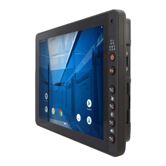
Chapter 2: Introduction 2.3.2 Front View with FM12E-V No Item Description 12.1‖ Touch Screen Acts as one of the inputs for the device Camera and 2 Megapixel front camera with a microphone for voice communication and Microphone voice recording Wireless communication indicators Defroster indicators (Defroster is customized feature available by request) Light Sensor and... -
Page 16: Front View With Fm14E-V
FM-V Series Vehicle Mounted Computer User Guide 2.3.3 Front View with FM14E-V No Item Description 14‖ Touch Screen Acts as one of the inputs for the device Camera 2 Megapixel front camera Microphone For voice communication and voice recording Wi-Fi Indicators... -
Page 17: Rear View With Fm10E-V And Fm12E-V
Chapter 2: Introduction 2.3.4 Rear View with FM10E-V and FM12E-V No Item Description VESA Mount Hole VESA 75, 100, and RAM Mount... -
Page 18: Rear View With Fm14E-V
FM-V Series Vehicle Mounted Computer User Guide 2.3.5 Rear View with FM14E-V No Item Description Power Button Press and hold the button for 3 second to turn on the device Function buttons Programmable Function keys that can be configured by using the Win- Set®... -
Page 19: Side View
Chapter 2: Introduction 2.3.6 Side View No Item Description LAN Port Connect to a local area network (LAN) using an Ethernet cable and provide optional PSE with 30W. D-SUB A: DB9 male with Connect a peripheral device such as a printer or scanner with serial port . -
Page 20: Top And Bottom View
FM-V Series Vehicle Mounted Computer User Guide 2.3.7 Top and Bottom View Item Description WWAN Antenna Connect a WWAN external antenna and allow the device to be Connector(optional) remotely mounted on the vehicle. (Optional) GPS Antenna Connect a GPS external antenna and allow the device to be Connector(optional) remotely mounted on the vehicle. -
Page 21: Chapter 3: Hardware
This chapter describes system hardware of FM-V Series Vehicle Mount Computer. 3.1 Central Processing Unit The FM-V Series VMC is running an Intel Elkhart Lake x6425E Processor, 2.0 GHz, and the operating system of this device is Windows 10. 3.2 Input and Output Connectors The FM-V Series device supports the following I/O connectors: •... -
Page 22: Power Cable Installation
Wiring Instruction 1. Place the device on the vehicle dock and make sure the device is Off. 2. Connect the power cable to the FM-V Series by aligning the connector pins and then push it, twist to fasten the connection. -
Page 23: Connecting The Power Cable For Installation On The Vehicle
Chapter 3: Hardware 3.7.3 Connecting the power cable for installation on the vehicle WARNING! / AVERTISSEMENT! Select a mounting location and make sure it is not located on the outside the vehicle. Sélectionnez un emplacement de montage et assurez-vous qu'il ne se trouve pas à l'extérieur du véhicule. - Page 24 FM-V Series Vehicle Mounted Computer User Guide Warning! When power is on, ignition pin connects to battery V+ will cause the power consumption even ignition is off Power cable description: Color Symbol VCC+ Black VCC- Green Ground White Ignition input (optional) With Ignition Function 7.
-
Page 25: Power Management Mode
3.8.1 Full ON Mode When the FM-V Series VMC is attached to either vehicle power or an external power supply and the power button is pressed, the device is in the ―ON‖ mode. In this mode, the keypad, touch screen and any attached peripherals will function normally. -
Page 26: Off Mode
3.8.4 OFF Mode By default, the FM-V Series VMC turns off if the user turns off the device through the system or presses the power button for 8 seconds with a critical shut down. The FM-V Series VMC will also be off when there is no connection to a power source or the UPS battery is depleted. -
Page 27: Power Control
Chapter 3: Hardware 3.9 Power Control 3.9.1Power Button FM10E-V FM14E-V FM12E-V Power button is located at the lower right side of the FM10E-V. Power button is located at the higher right side of the FM12E-V. Power button is located at the rear side of the FM14E-V. ... -
Page 28: Battery
There is a risk of an explosion caused by incorrect installation or misapplication of the battery pack. To avoid possible injury: Use only the type of the battery recommended by Winmate. Follow battery pack installation instructions in this user manual. ... -
Page 29: Backup Battery
IMPORTANT: The battery is consumable part. Therefore, it is recommended to replace the battery pack every two years with a new one recommended by Winmate. Contact our Service Center or sales representatives for more information on replacing the battery pack. -
Page 30: External Connectors
FM-V Series Vehicle Mounted Computer User Guide 3.11 External Connectors Power OFF the FM-V Series VMC before connecting cables to any port. 3.11.1 Serial Connector(COM1 & COM2) Signal Description Data Carrier Detect – Input Receive Data – Input Transmit Data – Output Data Terminal Ready –... -
Page 31: Dido / Serial Connector (Com1) (Optional)
Chapter 3: Hardware 3.11.2 DIDO / Serial Connector (COM1) (Optional) The Serial and DIDO connector is a DB-15 male connector located on the left side of the device. The connector supports a DIDO cable or a COM port cable. -
Page 32: Audio / Serial Connector (Com1) (Optional)
FM-V Series Vehicle Mounted Computer User Guide 3.11.3 Audio / Serial Connector (COM1) (Optional) The Serial and Audio connector is a DB-15 male connector located on the left side of the device. The connector supports a Audio cable or a COM port cable. -
Page 33: Can Bus / Serial Connector (Com2) (Optional)
Chapter 3: Hardware 3.11.4 CAN Bus / Serial Connector (COM2) (Optional) The Serial and CANBus connector is a DB-15 female connector located on the right side of the device. The connector supports a CANBus cable or a COM port cable. -
Page 34: Usb 2.0 Connector
FM-V Series Vehicle Mounted Computer User Guide 3.11.5 USB 2.0 Connector Signal Description CN1-1 CN1-2 White CN1-3 Green CN1-4 Black 3.11.6 LAN Connector Pin No. Signal Pin No. Signal TX_D1+ TX_D1- RX_D2+ BI_D3+ BI_D3- RX_D2- BI_D4+ BI_D4- 3.11.7 Power Connector... -
Page 35: External / Vehicle Remote Antenna
Chapter 3: Hardware 3.12 External / Vehicle Remote Antenna The FM-V Series is equipped with SMA Connector for additional external antenna (optional WWAN and GPS), to install the antenna please perform the following: 1. Remove the rubber cap on the SMA connector before installing the antenna. -
Page 36: Keyboard Options
FM-V Series Vehicle Mounted Computer User Guide 3.13 Keyboard Options The integrated keypad contains several programmable keys, which are user-programmable keys. Key Mapping is configured via the Win-Set ® utility on the control panel. See the Programmable key to remap these keys. -
Page 37: Integrated Keypad For Fm12E-V
Chapter 3: Hardware 3.13.2 Integrated Keypad for FM12E-V The FM12E-V has eight programmable keys from F1 to F8. The default values for these keys are: Press these keys in this order Default Key Value F1+F2 Touch Keypad Lock/Unlock F2+F3 Brightness adjustment (Panel+keypad) F3+F4 Volume adjustment Long press on F1... -
Page 38: Integrated Keypad For Fm14E-V
F4 (Programmable Key 4) F4 Key 3.13.4 SB Keyboard / Mouse A standard USB keyboard or mouse can be attached to the FM-V Series VMC using the appropriate adapter cable. The cable attached to the device and provides USB connector. -
Page 39: Led Function
Chapter 3: Hardware 3.14 LED Function FM14E-V FM10E-V FM12E-V Indicator Type LED Behavior System State The Device has detected a network and is connecting Wi-Fi No Network connection The devices are successfully connected and active. Bluetooth The Bluetooth function is disabled The external power is plugged in and the UPS battery is being Orange charged... -
Page 40: Power Led
FM-V Series Vehicle Mounted Computer User Guide 3.14.1 Power LED Power LED of FM10E-V and FM12E-V is located on the power button. Power LED behavior is shown at the table below. Indicator Type LED Behavior System State Solid Red System off and in suspend mode... -
Page 41: Chapter 4: Software
Chapter 4: Software Chapter 4: Software 4.1 Setting Up Windows for the First Time This chapter details how to setup the Windows that may be installed on the tablet for the first time. Caution Make sure the battery is full charged before starting the Tablet Computer for the first time with internal battery power. - Page 42 FM-V Series Vehicle Mounted Computer User Guide 3. On the Here's the legal stuff screen, read through the disclosures, then tap Accept. 4. Windows will then try to connect to network. Tap Skip this step to continue without a wireless connection as you can then set up the network later.
- Page 43 Chapter 4: Software 6. To create a local account, type your User name, password, and Password hint in the fields provided, then tap Next. 7. The initial setup screens are complete, and the desktop is displayed. 8. Read any introductory screens describing features of your computer, and tap Next upon completing each.
-
Page 44: Control Panel
FM-V Series Vehicle Mounted Computer User Guide 4.3 Control Panel 4.3.1 Using the Touch Screen The touch screen is a touch-sensitive device that allows you to control and make selections on the device by controlling the location of the pointer on the screen. -
Page 45: Touch Lock
Chapter 4: Software 4.3.2 Touch Lock Press F1 and F2 simultaneously to perform touch lock. While the touch is locked, all function keys and touch will not be able to work, until you slide the bar to unlock the touch lock. Press F1 and F2 simultaneously one more time to perform unlock touch function, or you can slide the bar to unlock the touch lock. -
Page 46: Volume Adjustment
Slide to the right side to increase the volume and slide to the left side to decrease the volume. 4.3.4 Brightness There are several configuration options for the FM-V Series VMC display backlight: 4.3.4.1 Power Management The display backlight is controlled by power management. When the user activity timer expires, the display backlight is turned off. -
Page 47: Function Key Form To Access F6~F24
Chapter 4: Software 4.3.5 Function Key Form to access F6~F24 Notice that this function is for FM10E-V/FM12E-V and may not be present in your device. Press on Fn button to call the Fn key form of other function key, performing like the following picture. Long press on Fn button one more time, to call the Fn key form of other function key (F11~F24), performing like the following picture. -
Page 48: Win-Set Utility
FM-V Series Vehicle Mounted Computer User Guide 4.4 Win-Set Utility Win-Set ® is a program made by Winmate to control the main functions of the FM-V Series. In Win-Set ® user can check system information, control function button settings, configure blanking function, scanner wedge and defroster settings. -
Page 49: Win-Set Shortcut Setting
Chapter 4: Software 4.4.2 Win-Set Shortcut Setting Long pressing on F1 button opens a Win-Set ® . In Function Buttons submenu user can set up functions of the function keys. Press the button next to F1, user will see the window show up just like the below picture. Then choose a program to be opened by button F1 next time. - Page 50 FM-V Series Vehicle Mounted Computer User Guide In this example Dbgview program will be opened by pressing F1. If user wants to delete this function, please press the button next to F1 in the Win-Set ® Function Buttons menu. Then there will be a window show up at the center of the desktop and ask you to confirm whether you want...
-
Page 51: Blanking Function
Chapter 4: Software 4.4.3 Blanking Function Winmate® FM-V Series equipped with screen blanking function. Once activated, it will lock the screen display to prevent or restrict the use of the in-vehicle computer. Open Blanking Function menu to control blanking behavior, sensitivity and debounce time. -
Page 52: Scanner Wedge
FM-V Series Vehicle Mounted Computer User Guide 4.4.4 Scanner Wedge Scanner wedge allows user to choose how to interface the Barcode Scanner to the FM-V Series. Item Setting Setting Options Description None Choose None, COM1 or COM2 and press Set ... -
Page 53: Defroster(Optional)
Chapter 4: Software 4.4.5 Defroster(Optional) In cold storage, outdoor or in intermodal facilities condensation may appear on the screen. A defroster clears condensation and thaw frost from the screen. Notice that Defroster is an optional feature for the FM10E-V / FM12E-V and may not be present in your device. To show the defroster status open Win-Set and go to the Defroster sub-menu to see the information about the defroster. -
Page 54: Ignition Software Ap
FM-V Series Vehicle Mounted Computer User Guide 4.5 Ignition Software AP Ignition Software AP is a program made by Winmate to control the ignition, COMport, and DIDO functions of the FM-V Series. To launch the Ignition Software AP, press and tap on Ignition Software AP Icon. Operations and functions on each menu options are explained in detail in the coming section. -
Page 55: Com Port Controller
Chapter 4: Software 4.5.2 COM port Controller Tap on the Ignition Software AP Icon and choose Launch Advanced Window. Then you can set COM1/COM2 to RS232, RS422, or RS485. -
Page 56: Opening My Bluetooth
FM-V Series Vehicle Mounted Computer User Guide 4.6 BT Your device has integrated BT capabilities for short-range wireless communication between BT - enabled devices. You can transfer files, playback audio, configure virtual serial ports, and share network connection via Bluetooth. -
Page 57: The Vmc With Label
Chapter 4: Software 4.7.1 The VMC with Label If this device has a BT address barcode label attached, follow these steps: Scan the paired BT address barcode label using the BT mobile scanner. If this is the first time the BT scanner has scanned the BT label on your device, the devices are automatically paired. -
Page 58: Connecting To A Wireless Network
FM-V Series Vehicle Mounted Computer User Guide NOTE: Note that user can also turn the wireless antenna on or off in Windows Mobility Center (Tap Start > Control Panel > Hardware and Sound > Windows Mobility Center). 4.8.1 Connecting to a Wireless network Perform the following to connect to a wireless network: 1. -
Page 59: Wwan(Optional)
Chapter 4: Software 4.9 WWAN(Optional) For vehicle computers equipped with wireless WAN (4G/LTE) card, to use the wireless WAN feature to connect to the network, perform the following procedure: Long press F4 to launch the RF Power Control utility. Tap on the Device button. Check the status of the WWAN. - Page 60 FM-V Series Vehicle Mounted Computer User Guide Item Icon Description Green: network is on. Red: network is off. On/Off Green: Indicate the network signal strength. More lit bars indicate stronger signal Red: No signal. Signal Strength Indicates the network connection type.
-
Page 61: Using Camera Features
Chapter 4: Software 4.10 Using Camera Features Your device has a built-in camera. This section explains how to use camera for taking pictures and making videos. 4.10.1 The Camera Screen Item Description Tap to record videos Video Tap to capture photos Photo Tap to select the destination folder to save captured photos and videos, Settings... -
Page 62: Recording Videos
FM-V Series Vehicle Mounted Computer User Guide The preview screen automatically closes after 3 seconds. Alternatively, do one of the following: • to delete the photo and return to the camera screen • to close the preview and return to the camera screen 4.10.3 Recording Videos... -
Page 63: Camera Settings
Chapter 4: Software 4.10.4 Camera Settings 1. Tap to open the setting page. 2. Modify necessary settings. 3. When settings are complete, tap OK to apply and save change. Item Description Check one of the check boxes to show the preview screen right after capturing a photo. -
Page 64: Using Recovery Wizard To Restore Computer
FM-V Series Vehicle Mounted Computer User Guide 4.11 Using Recovery Wizard to Restore Computer The FM-V Series computer has a dedicate recovery partition stored on the hard drive of the vehicle computer to enable quick one-key recovery process. This partition occupies about 11GB of the storage space, and comes built-in to each FM-V Series vehicle computer. - Page 65 Chapter 4: Software 5. Wait till the recovery process to complete. During the recovery process, a command prompt will show up to indicate the percent of recovery process. After recovery is completed, and the vehicle computer will restart automatically.
-
Page 66: Chapter 5: Accessories Installation
FM-V Series Vehicle Mounted Computer User Guide Chapter 5: Accessories Installation 5.1 Installing a SIM Card The Vehicle mounted computer supports data connection using 3G or 4G/LTE SIM cards and fits nano-SIM card. (Note: 4G/LTE feature is optional). Perform the following to install the SIM card to your vehicle... -
Page 67: Installing A Micro Sd Card
Chapter 5: Accessories Installation 5.2 Installing a Micro SD Card Micro SD card can be used to store files in the vehicle mounted computer, user can copy / download / upload files to and from the VMC. Perform the following to install the SIM card to your device. 1. -
Page 68: Chapter 6: Vehicle Mounting
Chapter 6: Vehicle Mounting 6.1 Vehicle Mount Instruction Make sure that the FM-V Series VMC does not obstruct the driver‘s vision and ensures safe driving. The general steps to mount the device on the vehicle are as follows: 1. Install RAM mount to the vehicle. - Page 69 Chapter 6: Vehicle Mounting Mounting 1 – No Drill Solution Component RAM Mount Part Number Description RAM Clamp Mounts - Clamp base with 2.25‖ Ball RAM-D-247U-4 on the forklift Arm for 2.25‖ Ball(L:8.375‖) RAM Arm RAM-D-201U RAM Ball on 75x75mm VESA with 2.25‖ Ball RAM-D-2461U device side Screw...
- Page 70 FM-V Series Vehicle Mounted Computer User Guide Mounting 2 – Drill Solution Component RAM Mount Part Number Description RAM round base 3.68‖ Round Base with 2.25‖ Ball mounts - on the RAM-D-202U forklift A1-1 Screw SUS304 M8 x 40mm Screw Arm for 2.25‖...
- Page 71 Chapter 6: Vehicle Mounting Mounting 3 – Keyboard Mounting Installation RAM Mount Component Part Description Number Winmate Keyboard Adapter 4 VESA Holes on the plate to Plate device and 4 AMPS holes to (designed by Winmate) RAM Ball Screw SUS304 M5 x 20mm Screw...
- Page 72 FM-V Series Vehicle Mounted Computer User Guide Keyboard Assembly This part shows the steps to install the keyboard. 1. Fasten all four screws on the RAM mount ball on the back of the keyboard. 2. Fasten the keyboard adapter on the other end of the RAM mount ball.
-
Page 73: Appendix A: Technical Specifications
Appendix A: Technical Specifications Appendix A: Technical Specifications FM10E-V FM10E-V System Specifications Processor Intel Elkhart Lake x6425E Processor, 2.0 GHz System Memory 4GB SODIMM DDR4-3200 (up to 8GB) Storage 128GB M.2 SSD (up to 256 GB) Operating System Windows 10 IoT Enterprise Security TPM 2.0 Display Specifications... -
Page 74: Fm12E-V
FM-V Series Vehicle Mounted Computer User Guide FM10E-V 1 x Micro SD Card Slot 6 x LED Indicator (WiFi, BT, UPS battery, HDD, Screen Blanking, Heater) 1 x Dual nano-SIM Card Slot 1 x CANBus(optional) 2 x RS232/422/485(Default RS232) 1 x Audio(Mic in or Line Out) either one with DIDO (Optional) 1 x Gigabit LAN port PSE (IEEE 802.3at 30W) (Optional) -
Page 75: Fm14E-V
Appendix A: Technical Specifications FM12E-V Humidity 5% to 90% RH, non-condensing IP Proof IP65 Impact Support EN62262 IK07 rating Shock MIL-STD-810H Method 516.8 Procedure I Vibration MIL-STD-810H Method 516.8 Procedure I Compliant with EN 6100042, enhanced ESD to ±12kV direct & ±15kV air. Standards and Certifications CE, FCC, UL609501, EN609501, PTCRB, Certification... - Page 76 FM-V Series Vehicle Mounted Computer User Guide FM14E-V GPS/GLONASS(Optional) WWAN 4G/LTE (Optional) Data Capture Camera 2MP Camera at front side Mechanical Specifications Dimensions (W x L x H) 342 x 225 x 52 mm Housing Magnesium Alloy housing with fanless design Weight 2.5kg...
- Page 77 NOTE...
- Page 78 NOTE...
- Page 79 NOTE...
- Page 80 Winmate Inc. 9F, No.111-6, Shing-De Rd., San-Chung District, New Taipei City 24158, Taiwan, R.O.C www.winmate.com Copyright © 2022 Winmate Inc. All rights reserved.
Need help?
Do you have a question about the FM-V Series and is the answer not in the manual?
Questions and answers