Table of Contents

Subscribe to Our Youtube Channel
Related Manuals for Winmate FM12E


Summary of Contents for Winmate FM12E
- Page 1 Vehicle Mounted Computer Intel Elkhart Lake x6425E Processor, 2.0 GHz FM12E User Guide Version 1.3 Document Part No. 9152111I103F Please read these instructions carefully before using this product, and save this manual for future use.
-
Page 2: Table Of Contents
FM12E Vehicle Mounted Computer User Guide Contents Chapter 1: Read Me First ........................... 7 1.1 Informations de sécurité (FR) ......................8 1.2 Safety Information (EN) ........................8 1.3 About the Adapter ..........................9 1.4 Li-Ion Battery ............................9 1.5 General Guideline ..........................9 Chapter 2: Introduction .......................... - Page 3 4.4 BT ..............................45 4.4.1 Opening My BT ........................... 45 4.5 BT Barcode Reader Setup ........................ 45 4.5.1 The FM12E with Label ........................ 46 4.5.2 The FM12E without Label ......................46 4.5.3 Adding and Pairing a BT Device ....................46 4.6 WLAN ...............................
- Page 4 Warranty Winmate Inc. warrants that each of its products is free from material and workmanship defect for a period of one year starting from the invoice date. If the customer discovers a defect, Winmate Inc. will, at its option, repair or replace the defective product at no charge to the customer, provided it is returned during the warranty period, with transportation charges prepaid.
- Page 5 FM12E Vehicle Mounted Computer User Guide Advisory Conventions Four types of advisories are used throughout the user manual to provide helpful information or to alert you to the potential for hardware damage or personal injury. These are Notes, Important, Cautions, and Warnings.
- Page 6 Chapter 1: Read Me First CE Notice (European Union) This device has been tested and found to conform to the limits set for a Class B product. EN 55022 — “Limits and Methods of Measurement of Radio Interference Characteristics of Information •...
- Page 7 FM12E Vehicle Mounted Computer User Guide IC Radiation Exposure Statement This EUT is compliance with SAR for general population/uncontrolled exposure limits in IC RSS-102 and had been tested in accordance with the measurement methods and procedures specified in IEEE 1528...
-
Page 8: Chapter 1: Read Me First
Chapter 1: Read Me First Chapter 1: Read Me First Follow and adhere to all warnings and instructions in this manual. For your safety, please read all safety and operating instructions before using the product. Keep this manual for future reference. CAUTION/ ATTENTION Pour réduire le risque d’incendie ou de choc électrique ne pas exposer l’appareil à... -
Page 9: Informations De Sécurité (Fr)
FM12E Vehicle Mounted Computer User Guide 1.1 Informations de sé curité (FR) Suivez et respectez tous les avertissements et instructions figurant sur l’écran. Pour votre sécurité, s’il vous plaît lire toutes les consignes de sécurité et de fonctionnement avant d’utiliser le device. Gardez ce manuel pour référence future. -
Page 10: About The Adapter
IMPORTANT: The battery is consumable part. Therefore, it is recommended to replace the battery pack every two years with a new one recommended by Winmate. Contact our Service Center or sales representatives for more information on replacing the battery pack. -
Page 11: Chapter 2: Introduction
FM12E is designed to easily be removed from the dock with a latch on the top of the FM12E vehicle docking. Since the dock remains attached to the vehicle, this device can easily be moved or switched from one vehicle to another vehicle. -
Page 12: Package Contents
Chapter 2: Introduction 2.1 Package Contents Before using this device, make sure that all the items listed below are present in your package: Dock + Latch Power Cable with Power Converter Computer FM10 USB Cable Locking Key Fuse Kit Cable 84W Adapter with Cable Clamp Kit WLAN Antenna x 2 Quick Start Guide Driver CD... -
Page 13: Components
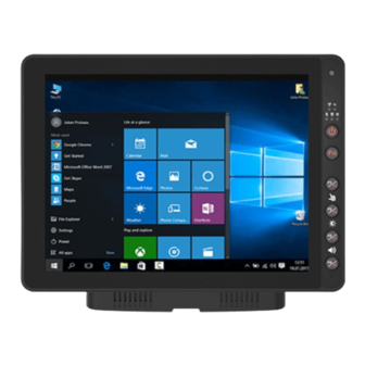
FM12E Vehicle Mounted Computer User Guide 2.3 Components 2.3.1 Front View No Item Description 12.1” Touch Screen Acts as one of the inputs for the device Camera and 2 Megapixel front camera with a microphone for voice communication and Microphone... -
Page 14: Rear View With Vehicle Dock
Chapter 2: Introduction 2.3.2 Rear View with Vehicle Dock No Item Description Release Latch Press to release the device and the docking VESA Mount Hole VESA 75, 100, and RAM Mount Kensington Lock Connect to a security lock, protecting your device from being stolen Power switch Set the switch to on (I) to provide the supply power to the device and it will automatically connect to the ignition system of the vehicle... -
Page 15: Side View With Vehicle Dock
FM12E Vehicle Mounted Computer User Guide 2.3.3 Side View with Vehicle Dock Left Side Right Side No Item Description WLAN Antenna Connect a WLAN external antenna and allow the device to be remotely Connector mounted on the vehicle GPS Antenna Connector Connect a GPS external antenna and allow the device to be remotely mounted on the vehicle. -
Page 16: Top And Bottom View
Chapter 2: Introduction 2.3.4 Top and Bottom View No Item Description Lock Lock the tablet in place Reading Light Use to provide illumination in dark environment... -
Page 17: Chapter 3: Hardware
Chapter 3: Hardware 3.1 System Hardware 3.2 Central Processing Unit The FM12E is running an Intel Elkhart Lake x6425E Processor, 2.0 GHz, and the operating system of this device is Windows 10. 3.3 Input and Output Connectors The FM12E device supports the following I/O connectors: •... -
Page 18: Audio Interface
To perform the connection, simply plug one end of the adapter cable to the dock and then plug the other end of the adapter cable to the DC output cable from adapter. For Details, refer to the connection diagram shown below: No Item AC Input Cable DC Output Cable To DC Output Cable To FM12E... -
Page 19: Power Management Mode
3.9.1 Full ON Mode When the FM12E is attached to either vehicle power or an external power supply, or it is operating from the UPS battery and the power button is pressed, the device is in the “ON” mode. In this mode, the keypad, touch screen and any attached peripherals will function normally. -
Page 20: Off Mode
By default, the FM12E turns off if the user turns off the device through the system or presses the power button for 8 seconds with a critical shut down. The FM12E will also be off when there is no connection to a power source or the UPS battery is depleted. -
Page 21: Power Control
NOTE: • The FM12E has to be docked in a powered vehicle docking station or UPS battery has to have a sufficient charge to power the device. • If no external power available and the UPS battery do not have enough charge, pressing... -
Page 22: Battery
There is a risk of an explosion caused by incorrect installation or misapplication of the battery pack. To avoid possible injury: • Use only the type of the battery recommended by Winmate. • Follow battery pack installation instructions in this user manual. •... -
Page 23: Backup Battery
The backup battery should be replaced only be authorized service personnel. 3.12 External Connectors Power OFF the FM12E before connecting cables to any port. Most of the external connectors for the FM12E are located on the vehicle dock. COM1 connects to a device such as printer or scanner. -
Page 24: Serial Connector (Com)
Chapter 3: Hardware 3.12.1 Serial Connector (COM) Signal Description Data Carrier Detect – Input Receive Data – Input Transmit Data – Output Data Terminal Ready – Output Signal / Power Ground Data Set Ready – Input Request to send – Output Clear to send –... -
Page 25: Can Bus / Audio Connector
The CAN Bus/ Audio connector is a D-15 male connector located on the rear side of the Vehicle Dock. The connector supports a headset adapter cable or a CAN BUS cable. The FM12E does not support connecting audio and CAN BUS simultaneously. - Page 26 Chapter 3: Hardware CAN Bus Cable Pin No. Signal Pin No. Signal CN1-A CAN_GND CN3-3 CAN_GND CN2-A CAN_GND CN1-B CAN_V+ CAN3-15 CN2-B CAN_V+ CN1-C CAN_H CN3-13 CAN_H CN2-C CAN_H CN1-D CAN_L CN3-2 CAN_L CN2-D CAN_L CN1-E CAN_SHLD CN3-12 CAN_SHLD CN2-E CAN_SHLD CN3-5 CN3 SHELL...
- Page 27 FM12E Vehicle Mounted Computer User Guide Audio Connector Signal Description CN4-1 CN4-2 CN4-3 CN4-4 CN4-5 AUGND Optional ground CN4-6 HP_R Headset return CN4-7 HP_L Headset output CN4-8 MIC_L Microphone input CN4-9 CN4-10 HP_JD CN4-11 - CN4-12 - CN4-13 - CN4-14 -...
-
Page 28: Lan Connector
Chapter 3: Hardware 3.12.4 LAN Connector Pin No. Signal Pin No. Signal TX_D1+ TX_D1- RX_D2+ BI_D3+ BI_D3- RX_D2- BI_D4+ BI_D4- 3.12.5 Power Connector 1. Power Connector 2. Power Switch Power Connector Pin No. SYMBOL CN2-1 VIN + CN2-2 VIN + CN2-3 VIN - CN2-4... -
Page 29: Antenna Connections
The FM12E equipped with internal antennas on the computer side as well as external antennas on the Vehicle Dock side. When the FM12E Computer is on the Vehicle Dock, it will by default use the external antennas on the Dock that are attached through the SMA Connectors for better signal strength. Only when the FM12E computer is removed from the dock will it use the internal antennas. -
Page 30: Keyboard Options
Chapter 3: Hardware 3.14 Keyboard Options 3.14.1 Integrated Keypad The integrated keypad contains ten programmable keys, F1~ F8 are user programmable keys. Key Mapping ® is configured via the Win-Set utility on the control panel. See Programmable key to remap these keys. The default values for these keys are: Press these keys in this order Default Key Value... -
Page 31: Usb Keyboard / Mouse
FM12E Vehicle Mounted Computer User Guide 3.14.2 USB Keyboard / Mouse A standard USB keyboard or mouse can be attached to the FM12E using the appropriate adapter cable. The cable attached to the device and provides USB connector. 3.15 LED Function LED indicators are located on the right side of the front panel. -
Page 32: Display
The FM12E’s display measures 12.1 inches diagonally, display resolution is 1024 x 768-pixel resolution and bonded with resistive touch. A unique feature here is that the FM12E supports screen blanking to eliminate driver distraction when the vehicle is in motion. -
Page 33: Chapter 4: Software
FM12E Vehicle Mounted Computer User Guide Chapter 4: Software 4.1 Setting Up Windows for the First Time This chapter details how to setup the Windows that may be installed on the tablet for the first time. Caution Make sure the battery is full charged before starting the Tablet Computer for the first time with internal battery power. - Page 34 Chapter 4: Software 3. On the Here's the legal stuff screen, read through the disclosures, then tap Accept. 4. Windows will then try to connect to network. Tap Skip this step to continue without a wireless connection as you can then set up the network later. 5.
- Page 35 FM12E Vehicle Mounted Computer User Guide 6. To create a local account, type your User name, password, and Password hint in the fields provided, then tap Next. 7. The initial setup screens are complete, and the desktop is displayed. 8. Read any introductory screens describing features of your computer, and tap Next upon...
-
Page 36: Control Panel
Chapter 4: Software 4.2 Control Panel 4.2.1 Using the Touch Screen The touch screen is a touch-sensitive device that allows you to control and make selections on the device by controlling the location of the pointer on the screen. NOTE: Do not use sharp or pointed objects on the touch screen. -
Page 37: Touch Lock
FM12E Vehicle Mounted Computer User Guide 4.2.2 Touch Lock Press F1 and F2 simultaneously to perform touch lock. While the touch is locked, all function keys and touch will not be able to work, until you slide the bar to unlock the touch lock. -
Page 38: Brightness
Chapter 4: Software 4.2.3 Brightness There are several configuration options for the FM12E display backlight: 4.2.3.1 Power Management The display backlight is controlled by power management. When the user activity timer expires, the display backlight is turned off. 4.2.3.2 Display and Keypad Backlight Brightness The intensity of the display backlight can be manually configured: 1. -
Page 39: Volume Adjustment
FM12E Vehicle Mounted Computer User Guide 4.2.4 Volume Adjustment Press F3 and F4 simultaneously to perform volume adjustment. The adjustment slide bar will appear on screen transparently. Slide to the right side to increase the volume and slide to the left side to decrease the... -
Page 40: Win-Set Utility
Chapter 4: Software 4.3 Win-Set Utility Win-Set ® is a program made by Winmate to control the main functions of the FM12E. In Win-Set ® user can check system information, control function button settings, configure blanking function, scanner wedge and defroster settings. - Page 41 FM12E Vehicle Mounted Computer User Guide Press the button next to F1, user will see the window show up just like the below picture. Then choose a program to be opened by button F1 next time. In this example Dbgview program will be opened by pressing F1.
- Page 42 Chapter 4: Software Then there will be a window show up at the center of the desktop and ask you to confirm whether you want to delete this function or not. Then press Yes to finish this step.
-
Page 43: Blanking Function
FM12E Vehicle Mounted Computer User Guide 4.3.3 Blanking Function Winmate® FM12E equipped with screen blanking function. Once activated, it will lock the screen display to prevent or restrict the use of the in-vehicle computer. Open Blanking Function menu to control blanking behavior, sensitivity and debounce time. -
Page 44: Scanner Wedge
Chapter 4: Software 4.3.4 Scanner Wedge Scanner wedge allows user to choose how to interface the Barcode Scanner to the FM12E. Item Setting Setting Options Description • None Choose None, COM1 or COM2 and press Set • Ports COM1 •... -
Page 45: Defroster
In cold storage, outdoor or in intermodal facilities condensation may appear on the screen. A defroster clears condensation and thaw frost from the screen. Notice that Defroster is an optional feature for the FM12E and may not be present in your device. -
Page 46: Opening My Bt
Chapter 4: Software 4.4 BT Your device has integrated BT capabilities for short-range wireless communication between BT- enabled devices. You can transfer files, playback audio, configure virtual serial ports, and share network connection via BT. By default, the BT feature is enabled as indicated by the BT icon on the taskbar. To Enable the Wireless BT feature, perform the following procedure: Long press the F2 to launch the RF Power Control utility application. -
Page 47: The Fm12E With Label
FM12E Vehicle Mounted Computer User Guide 4.5.1 The FM12E with Label If this device has a BT address barcode label attached, follow these steps: Scan the paired BT address barcode label using the BT mobile scanner. If this is the first time the BT scanner has scanned the BT label on your device, the devices are automatically paired. -
Page 48: External Wlan Antenna
Chapter 4: Software NOTE: Note that user can also turn the wireless antenna on or off in Windows Mobility Center (Tap Start > Control Panel > Hardware and Sound > Windows Mobility Center). 4.6.1 External WLAN Antenna The default setting of the WLAN antenna is auto-switch, means when the device is on the dock, the device will detect the WLAN antenna on the dock;... -
Page 49: Wwan
FM12E Vehicle Mounted Computer User Guide 4.7 WWAN For vehicle computers equipped with wireless WAN (4G/LTE) card, to use the wireless WAN feature to connect to the network, perform the following procedure: Long press F4 to launch the RF Power Control utility. - Page 50 Chapter 4: Software Item Icon Description • Green: network is on. • Red: network is off. On/Off • Green: Indicate the network signal strength. More lit bars indicate stronger signal • Red: No signal. Signal Strength Indicates the network connection type. Network Type Toolbar Tap an icon to access the function.
-
Page 51: Using Camera Features
FM12E Vehicle Mounted Computer User Guide 4.8 Using Camera Features Your device has a built-in camera. This section explains how to use camera for taking pictures and making videos. 4.8.1 Opening the Camera Perform one of the following to open the camera: •... -
Page 52: Recording Videos
Chapter 4: Software The preview screen automatically closes after 3 seconds. Alternatively, do one of the following: • to delete the photo and return to the camera screen • to close the preview and return to the camera screen 4.8.4 Recording Videos 1. -
Page 53: Camera Settings
FM12E Vehicle Mounted Computer User Guide 4.8.5 Camera Settings 1. Tap to open the setting page. 2. Modify necessary settings. 3. When settings are complete, tap OK to apply and save change. Item Description Check one of the check boxes to show the preview screen right after capturing a photo. -
Page 54: Using Recovery Wizard To Restore Computer
4.9 Using Recovery Wizard to Restore Computer The FM12E computer has a dedicate recovery partition stored on the hard drive of the vehicle computer to enable quick one-key recovery process. This partition occupies about 11GB of the storage space, and comes built-in to each FM12E vehicle computer. - Page 55 FM12E Vehicle Mounted Computer User Guide 5. Wait till the recovery process to complete. During the recovery process, a command prompt will show up to indicate the percent of recovery process. After recovery is completed, and the vehicle computer will restart automatically.
-
Page 56: Chapter 5: Accessories Installation
Chapter 5: Accessories Installation Chapter 5: Accessories Installation 5.1 Installing a SIM Card The Vehicle mounted computer supports data connection using 3G or 4G/LTE SIM cards and fits nano-SIM card. (Note: 4G/LTE feature is optional). Perform the following to install the SIM card to your vehicle mounted computer: Remove the service window in the right side of the device by unscrewing two screws Remove the screw that is securing the service window, carefully lift the cover up... -
Page 57: Installing A Micro Sd Card
FM12E Vehicle Mounted Computer User Guide 5.2 Installing a Micro SD Card Micro SD card can be used to store files in the vehicle mounted computer, user can copy/ download/ upload files to and from the VMC. Perform the following to install the SIM card to your device. -
Page 58: Installing A Stylus With The Holder
Chapter 5: Accessories Installation 5.3 Installing a Stylus with the holder Notice that stylus is an optional feature for FM12E vehicle mounted computer. Perform the following to dock the device Align the screw hole between the stylus holder and the rear side of device; fasten it with the given screw. -
Page 59: Chapter 6: Vehicle Mounting
Chapter 6: Vehicle Mounting 6.1 Introduction The FM12E is designed to be mounted to a docking station on the vehicle with RAM mount. The vehicle mount holds the dock and FM12E attaches to the dock. The FM12E can operate on another vehicle equipped with the docking station without the need to mount the device again. -
Page 60: Ram Mount Installation
Chapter 6: Vehicle Mounting 6.3 RAM Mount Installation Winmate recommends using RAM Mounting Parts as part of our device mounting solution. The rear cover of this device is designed to be mounted to RAM Mount solutions, which provides different mounting options to fit any industrial use or vehicle. - Page 61 FM12E Vehicle Mounted Computer User Guide Mounting 2 – Drill Solution Component RAM Mount Part Number Description RAM round base 3.68” Round Base with 2.25” Ball mounts - on the RAM-D-202U forklift A1-1 Screw SUS304 M8 x 40mm Screw 2.25”...
- Page 62 2. Insert the ball on the dock into the RAM arm and tighten the knob. Mounting 3 – Keyboard Mounting Installation Component Mount Part Description Number Winmate Keyboard Adapter 4 VESA Holes on the plate to Plate device and 4 AMPS holes to (designed by Winmate) RAM Ball...
- Page 63 FM12E Vehicle Mounted Computer User Guide Keyboard Assembly This part shows the steps to install the keyboard. 1. Fasten all four screws on the RAM mount ball on the back of the keyboard. 2. Fasten the keyboard adapter on the other end of the RAM mount ball.
-
Page 64: Docking And Undocking The Device
The battery indicator is orange. the dock. CAUTION/ ATTENTION Always place the FM12E on the dock from top side. Placing from left or right sides may damage the docking connector. Perform the following to undock the device: While holding the device, push the release latch on the docking station and then lift the device to un-... -
Page 65: Power Cable Installation
Wiring Instruction 1. Place the device on the vehicle dock and make sure the device is Off. 2. Connect the CN2 to the FM12E vehicle dock by aligning the connector pins and then push it, twist to fasten the connection. -
Page 66: Connecting The Power Cable For Installation On The Vehicle
Chapter 6: Vehicle Mounting 6.2.3 Connecting the power cable for installation on the vehicle WARNING! / AVERTISSEMENT! This power cable should only be used on the 24, 36, or 48 Volt forklifts. Note that, this power cable cannot work for 12 Volt forklifts. Ce câble d'alimentation ne doit être utilisé... - Page 67 FM12E Vehicle Mounted Computer User Guide WARNING! AVERTISSEMENT! All power wiring must use the supplied power cable. Tout le câblage électrique doit utiliser le câble d'alimentation fourni. 4. Slide tubing over wires, remove the wires and insert it to the fuse holder, crimp it.
-
Page 68: Power Cable Routing
6.5.4 Power cable routing There are many cables available for the FM12E including power cable, CAN Bus cable, or USB cable. To secure these cables, there are five cable clamps secured the FM12E vehicle dock to prevent the cable strain. -
Page 69: Appendix A: Technical Specifications
FM12E Vehicle Mounted Computer User Guide Appendix A: Technical Specifications FM12E System Specifications Processor Intel Elkhart Lake x6425E Processor, 2.0 GHz System Memory 4GB SODIMM DDR4-3200 (up to 8GB) Storage 128GB M.2 SSD (up to 256 GB) Operating System Windows 10 IoT Enterprise Security TPM 2.0... -
Page 70: Appendix B: Order Information
The product shown in this datasheet is a standard model. For diagrams that contain customized or optional I/O, please contact the Winmate Sales Team for more information Appendix B: Order Information FM12E Series available in the following configurations: Built-in Heater FM12E... - Page 71 NOTE...
- Page 72 NOTE...
- Page 73 NOTE...
- Page 74 Winmate Inc. 9F, No.111-6, Shing-De Rd., San-Chung District, New Taipei City 24158, Taiwan, R.O.C www.winmate.com Copyright © 2022 Winmate Inc. All rights reserved.
Need help?
Do you have a question about the FM12E and is the answer not in the manual?
Questions and answers