Table of Contents
Advertisement
Quick Links
Advertisement
Table of Contents

Subscribe to Our Youtube Channel
Related Manuals for Winmate IBDRW100-P


Summary of Contents for Winmate IBDRW100-P
- Page 1 DIN Rail Box PC IBDRW100-P/ IBDRW100-EX-P Intel® Pentium® Processor N4200 1.1 GHz, up to 2.56 GHz User Manual Version 1.0 Document Part No. 917111101106 Please read this instructions carefully before using this product, and save this manual for future use.
-
Page 2: Table Of Contents
IBDRW100-P/ IBDRW100-EX-P User Manual Contents Preface ............................4 About This User Manual ......................7 Chapter 1: Introduction ......................8 1.1 Product Overview ......................8 1.2 Product Features ......................8 1.2 Accessories ........................9 1.3 Chassis Dimensions ...................... 10 1.4 Description of Parts ....................... 10 Chapter 2: Hardware Installation .................. - Page 3 Preface 4.2.7 Boot ........................... 37 4.2.8 Exit ..........................39 4.3 Using Recovery Wizard to Restore the System ............41 Chapter 5: Driver Installation ....................42 5.1 Chipset Driver Installation ..................... 42 5.2 Graphics Driver Installation ................... 44 5.3 TXE Driver Installation ....................48 5.4 Audio Driver Installation ....................
-
Page 4: Preface
IBDRW100-P/ IBDRW100-EX-P User Manual Preface Copyright Notice No part of this document may be reproduced, copied, translated, or transmitted in any form or by any means, electronic or mechanical, for any purpose, without the prior written permission of the original manufacturer. - Page 5 Preface Advisory Conventions Four types of advisories are used throughout the user manual to provide helpful information or to alert you to the potential for hardware damage or personal injury. These are Notes, Important, Cautions, and Warnings. The following is an example of each type of advisory. Note: A note is used to emphasize helpful information Important:...
- Page 6 Special Conditions of Use Winmate IBDRW100-EX-P is to be installed in an ATEX certified IP54 (as defined in EN 60079- 0 and EN 60079-15) enclosure and may be accessible only by the use of a tool. Provision shall be made to prevent the rated voltage being exceeded by the transient disturbances of more than 140% of the peak rated voltage.
-
Page 7: About This User Manual
About This User Manual About This User Manual This User Manual provides information about using the IBDRW100-P Series DIN Rail Box PC. This User Manual applies to the IBDRW100-P Series DIN Rail Box PC - IBDRW100-P/ IBDRW100-EX-P. The documentation set for the IBDRW100-P Series DIN Rail Box PC provides information for specific user needs, and includes: ... -
Page 8: Chapter 1: Introduction
Chapter 1: Introduction 1.1 Product Overview Winmate IBDRW100-P Series is a DIN-rail mounted Fanless Box PC, which provides several serial communication ports. With a compact size and small form factor as well as front accessible I/O port. The IBDRW100-P Series is very convenient for wiring and DIN-rail installation in the control cabinet. -
Page 9: Accessories
10 pin female 3 pin Connector connector for DIDO for Power Part No. 917111101106 Part No. 90ME01000000 Part No. 604530005D01 Part No.604520105001 Cable Holder Kit (only for IBDRW100-P-EX) Part No. 821118561K00 x 2 Part No 821118561K01 / Part No 821118561K02... -
Page 10: Chassis Dimensions
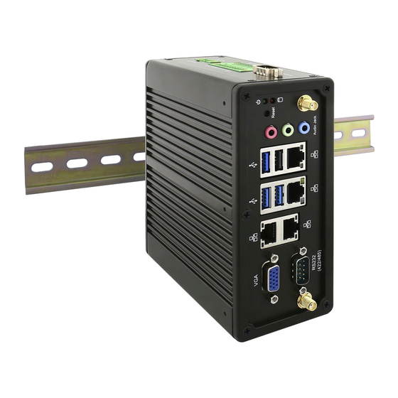
IBDRW100-P/ IBDRW100-EX-P User Manual 1.3 Chassis Dimensions Unit: mm 1.4 Description of Parts Front 1. VGA 2. RS232/422/485 3. LAN 4.LAN 5. USB 6. Audio Jack Rear 7. Isolated RS422 default (RS485 as optional) 8. DIDO 9. Power terminal Block (9-36V DC IN) -
Page 11: Chapter 2: Hardware Installation
STDA_SSTX- STDA_SSTX+ 2.1.2 USB 2.0 Connector The IBDRW100-P/ IBDRW100-EX-P provide one USB 2.0 connectors. Use USB 2.0 connector to connect external devices such as mouse or keyboard to the box computer. Pin assignment and signal names of USB connector Pin №... -
Page 12: Vga Connector
IBDRW100-P/ IBDRW100-EX-P User Manual 2.1.4 VGA Connector The IBDRW100-P/ IBDRW100-EX-P have one VGA DB15 connector. Use VGA cable to connect DIN-Rail Box Computer to external monitor. Pin assignment and signal names of VGA connector Pin № Pin № Signal Name... -
Page 13: Isolated Rs422/485 Connector
Chapter 2: Hardware Installation 2.1.6 Isolated RS422/485 Connector The IBDRW100-P/ IBDRW100-EX-P have one isolated COM1 9-pin D-sub connectors that offer RS-422/485 serial communication interface ports. Default setting is RS-422, but this can be modified by jumpers. Pin assignment and signal names of isolated RS-422/485 connector Pin №... -
Page 14: Dc Power 3Pin Terminal Block
IBDRW100-P/ IBDRW100-EX-P User Manual 2.1.9 DC Power 3pin Terminal Block The DC power source input of the IBDRW100-P/ IBDRW100-EX-P is a 3 pin terminal block connector that supports 9-36V DC power input. Pin assignment and signal names of DC power 3pin terminal block... -
Page 15: Chapter 3: Initial Setup
Chapter 3: Initial Setup Chapter 3: Initial Setup 3.1 DIN Rail Mounting Setup Please follow these steps to mount the IBDRW hook kit on a DIN rail Screw the provided DIN-rail Kit on the rear side of the box as the diagram shown below. -
Page 16: Cable Arm Bracket Installation (Optional For Ibdrw100-Ex-P)
IBDRW100-P/ IBDRW100-EX-P User Manual 3.2 Cable ARM Bracket Installation (Optional for IBDRW100-EX-P) In hazardous locations, sparks caused by the movement from a cable and connector which is even slightly loose could lead to a disaster and to prevent this, cable arm bracket can be use to secure some LAN, USB and Audio connectors. -
Page 17: Enclosure For Ibdrw100-Ex-P
User may also include secure mounting (hence the DIN Rail design) or mounting in specially designed enclosure boxes. The pictures below show an IP54-spec enclosure box Winmate uses for the IBDRW100-EX-P to meet ATEX and C1D2 certification. This enclosure box is... - Page 18 IBDRW100-P/ IBDRW100-EX-P User Manual Follow these steps before installing the IBDRW100-EX-P inside the enclosure box: Please check if the unit has been correctly installed without any damage Please check if the wiring and screws have been properly tightened Please check if the cable gland has been tightened...
-
Page 19: Chapter 4: Insyde Bios Setup
Chapter 4: Insyde BIOS Setup Chapter 4: Insyde BIOS Setup 4.1 BIOS Introduction 4.1.1 BIOS Setup and Boot Procedure BIOS stand for “Basic Input Output System” and it is the most basic communication between user and the hardware. To enter BIOS Setup, the [DEL] key must be pressed after the USB controller has been initialized as soon as the following message appears on the monitor during Power On Self-Test (POST): “Press DEL to run SETUP”... -
Page 20: Bios Menu
IBDRW100-P/ IBDRW100-EX-P User Manual Cursor → Goes to the next item 4.2 BIOS Menu 4.2.1 Main Immediately after the [DEL] key is pressed during startup, the main BIOS setup menu appears: BIOS Setting Description Setting Options Effect Language Select the current default... -
Page 21: Advanced
Chapter 4: Insyde BIOS Setup 4.2.3 Advanced BIOS Setting Description Setting Option Effect Setting Boot configuration Opens Boot Configuration Enter parameters submenu Setting Uncore configuration Opens Uncore Configuration Enter parameters submenu Setting South Cluster Opens South Cluster Configuration Enter Configuration parameters submenu Setting Security Configuration Opens... - Page 22 IBDRW100-P/ IBDRW100-EX-P User Manual 4.2.3.1 USB Configuration BIOS Setting Description Setting Option Effect OS Selection OS selection Windows/ Linux Select OS. Default: Based on your order.
- Page 23 Chapter 4: Insyde BIOS Setup 4.2.3.2 Uncore Configuration BIOS Setting Description Setting Option Effect VBT Hook VBT Hook Enabled/ Disabled Enables or disables Configuration Configuration VBT Hook configuration 2MB / 4MB / 8MB GTT Size Select GTT (Graphics Select GTT Size. Translation Table) Size Aperture Size...
- Page 24 IBDRW100-P/ IBDRW100-EX-P User Manual 4.2.3.3 South Cluster Configuration BIOS Setting Description Setting Option Effect PCI Express PCI Express Enter Opens sub-menu Configuration Configuration Settings SATA Drives SATA Drives Settings Enter Opens sub-menu USB Configuration USB Configuration Enter Opens sub-menu Settings...
- Page 25 Chapter 4: Insyde BIOS Setup 4.2.3.3.1 PCI Express Configuration BIOS Setting Description Setting Option Effect PCI Express Clock Enables or disables PCI Express Clock Gating Enable/ Enabled/ Disabled PCI Express Clock Gating Disable for each root Gating port Controls Peer-to- Enables or disables Peer Memory Write Peer Memory Read...
- Page 26 IBDRW100-P/ IBDRW100-EX-P User Manual...
- Page 27 Chapter 4: Insyde BIOS Setup 4.2.3.3.2 Chipset-SATA Controller Configuration BIOS Setting Description Setting Option Effect Enables or disables Enabled/ Enables or disables the Chipset SATA the Chipset SATA Disabled Chipset SATA Controller Controller Advanced Host Controller Interface (AHCI) mode AHCI enables the use of advanced features on SATA drives...
- Page 28 IBDRW100-P/ IBDRW100-EX-P User Manual 4.2.3.3.3 USB Configuration BIOS Setting Description Setting Option Effect Control each of the Enabled/ Enables or disables each USB Per-Port Control USB port (0~7) Disabled of the USB port enable/disable Disable the XDCI Enabled/ Enables or disables XDCI...
- Page 29 Chapter 4: Insyde BIOS Setup 4.2.3.3.4 Miscellaneous Configuration BIOS Setting Description Setting Option Effect Enabled/ High Precision Timer Enable or disable the High Precision Timer settings Disabled High Precision Timer 8254 Clock Gating Enabled/ Enable or disable8254 8254 Clock Gating settings Disabled Clock Gating...
- Page 30 IBDRW100-P/ IBDRW100-EX-P User Manual 4.2.3.4 Security Configuration BIOS Setting Description Setting Option Effect Select Target TPM Select Target TPM Target TPM device dTPM device device...
- Page 31 Chapter 4: Insyde BIOS Setup 4.2.3.5 Thermal Configuration BIOS Setting Description Setting Option Effect This value controls the temperature of the ACPI Set the point in which Critical Trip Point – the Critical Trip Point 125 C the OS will shut the point in which the OS will system off shut the system off...
- Page 32 IBDRW100-P/ IBDRW100-EX-P User Manual 4.2.3.6 S10 F81866A BIOS Setting Description Setting Option Effect Disabled No configuration Configure Serial port settings. Default settings: Serial Port A ~ Serial Port A: AUTO Enabled User configuration Serial Port D Serial Port B: AUTO...
- Page 33 Chapter 4: Insyde BIOS Setup...
-
Page 34: H2Ouve Configuration
IBDRW100-P/ IBDRW100-EX-P User Manual Hardware Monitor 4.2.4 H2oUve Configuration... -
Page 35: Security
Chapter 4: Insyde BIOS Setup BIOS Setting Description Setting Option Effect Enables or disables H2OUVE tool interface Enabled/ H2OUVE Support interface for H2OUVE settings Disabled tool 4.2.5 Security BIOS Setting Description Setting Option Effect TrEE Protocol 1.0 or 1.1 TrEE Protocol Version TrEE Protocol Version Version Configure TPM Availability... -
Page 36: Power
IBDRW100-P/ IBDRW100-EX-P User Manual 4.2.6 Power BIOS Setting Description Setting Option Effect Setting CPU Configuration CPU Configuration Enter Opens sub-menu parameters Power Management Even Power Management Wake on PME Force Enable from S5 state Even after S5 state Wake on RTC from... -
Page 37: Boot
Chapter 4: Insyde BIOS Setup 4.2.7 Boot... - Page 38 IBDRW100-P/ IBDRW100-EX-P User Manual BIOS Setting Description Setting Option Effect Select boot type to Dual Select boot type to Dual Dual/ Legacy Boot Type type, Legacy type or UEFI type, Legacy type or UEFI type UEFI type Allows InsydeH20 to...
-
Page 39: Exit
Chapter 4: Insyde BIOS Setup 4.2.8 Exit... - Page 40 IBDRW100-P/ IBDRW100-EX-P User Manual BIOS Setting Description Setting Option Effect Exit system setup and save Exit Saving Options Enter Opens sub-menu your changes Save Change Save changes without exit Enter Opens sub-menu Without Exit system setup Exit Discarding Exit system setup and...
-
Page 41: Using Recovery Wizard To Restore The System
Plug-in the AC adapter to Box PC. Make sure the Box PC stays plugged in to power source during the recovery process. Turn on the IBDRW100-P/ IBDRW100-EX-P DIN-Rail Box PC, and when the boot screen shows up, press the F6 to initiate the Recovery Wizard. ... -
Page 42: Chapter 5: Driver Installation
Follow the instructions below to complete the installation. You will quickly complete the installation. Step 1 Insert the CD that comes with the IBDRW100-P/ IBDRW100-EX-P DIN-Rail Box PC. Open the file “Chipset Driver”. Click SetupChiset. Step 2 Click Next to install driver. - Page 43 Chapter 5: Driver Installation Step 4 Check the License Agreement and click Accept to continue. Step 5 Check Readme File Information and click Install to continue. Step 7 Wait for the system to install the driver.
-
Page 44: Graphics Driver Installation
IBDRW100-P/ IBDRW100-EX-P DIN-Rail Box PC is equipped with Intel SoC Integrated Device. Follow the instructions below to complete the installation. You will quickly complete the installation. Step 1 Insert the CD that comes with the IBDRW100-P/ IBDRW100-EX-P DIN-Rail Box PC. - Page 45 Chapter 5: Driver Installation Step 2 Click Next to continue. Step 3 The system is extracting files. Please wait while the InstallShield Wizard extracts the files needed to install Intel Graphics Driver Software to your computer. This may take few moments. Step 4 Select automatically run WinSAT and enable the Windows Aero desktop theme (if supported) and click Next.
- Page 46 IBDRW100-P/ IBDRW100-EX-P User Manual Step 5 Check the License Agreement and click Yes to continue. Step 6 Check Readme File Information and click Install to continue. Step 6 Please wait while the following setup operations are performed.
- Page 47 Chapter 5: Driver Installation Step 7 Click Next to continue. Step 7 Select “Yes, I want to restart this computer now”, and click Finish.
-
Page 48: Txe Driver Installation
IBDRW100-P/ IBDRW100-EX-P User Manual 5.3 TXE Driver Installation Follow the instructions below to complete the TXE Driver installation. Step 1 Insert the CD that comes with the IBDRW100-P/ IBDRW100-EX-P DIN-Rail Box PC. Click SetupTXE. Step 2 Click Next to continue. - Page 49 Chapter 5: Driver Installation Step 3 Check the License Agreement, select “I accept the terms in the License Agreement” and click Next to continue. Step 4 Click Next to continue. Step 5 Please wait while the product is being installed.
-
Page 50: Audio Driver Installation
Step 6 Click Next to exit installation window. 5.4 Audio Driver Installation Follow the instructions below to complete the TXE Driver installation. Step 1 Insert the CD that comes with the IBDRW100-P/ IBDRW100-EX-P DIN-Rail Box PC. Open Audio folder. Click Setup. - Page 51 Chapter 5: Driver Installation Step 2 Click Next to continue. Step 3 Wait for the system to install files. Step 4 Select “Yes, I want to restart this computer now”, and click Finish.
-
Page 52: Lan Driver Installation
5.5 LAN Driver Installation Follow the instructions below to complete the LAN Driver installation. Step 1 Insert the CD that comes with the IBDRW100-P/ IBDRW100-EX-P DIN-Rail Box PC. Open LAN folder. Open archived file. Step 2 Installation is in progress. - Page 53 Chapter 5: Driver Installation Step 3 Click Next to continue. Step 4 Check the License Agreement, select “I accept the terms in the License Agreement” and click Next to continue. Step 5 Click Next to continue.
- Page 54 IBDRW100-P/ IBDRW100-EX-P User Manual Step 6 Wait for the system to install files. Step 7 Click Finish to exit installation window.
-
Page 55: Appendix
Appendix Appendix Appendix A: Hardware Specifications Model Name IBDRW100-P IBDRW100-EX-P System Intel® Pentium® N4200 1.1GHz, Intel® Pentium® N4200 1.1GHz, Specification up to 2.56GHz up to 2.56GHz System SO-DIMM socket DDR3L-1866 SO-DIMM socket DDR3L-1866 Memory Max. 8GB Max. 8GB 1 x SATAIII, 1 x M.2 (2242 KEY 1 x SATAIII, 1 x M.2 (2242 KEY... - Page 56 IBDRW100-P/ IBDRW100-EX-P User Manual Model Name IBDRW100-P IBDRW100-EX-P Mechanical Net Weight 6.5 kg (14.33 lbs) 6.5 kg (14.33 lbs) Specification Mounting DIN Rail DIN Rail Cooling Fanless Fanless Environment Operating -20˚ to 60˚C (-4˚ to 140˚F) -20˚ to 60˚C (-4˚ to 140˚F) Specification Temp.
-
Page 57: Appendix B: Approvals And Certifications
Appendix Appendix B: Approvals and Certifications Refer the following descriptions for various approvals and certifications N.A. Safety for Information Technology Equipment (Optional for IBDRW100-EX-P) Certification by Underwriter Laboratories to UL60950-1, 2 Edition standard and equivalent CSA C22.2 No 60950-1-07, 2 Edition Standard N.A. - Page 58 Notes ______________________________________________________________________________ ______________________________________________________________________________ ______________________________________________________________________________ ______________________________________________________________________________ ______________________________________________________________________________ ______________________________________________________________________________ ______________________________________________________________________________ ______________________________________________________________________________ ______________________________________________________________________________ ______________________________________________________________________________ ______________________________________________________________________________ ______________________________________________________________________________ ______________________________________________________________________________ ______________________________________________________________________________ ______________________________________________________________________________ ______________________________________________________________________________ ______________________________________________________________________________ ______________________________________________________________________________ ______________________________________________________________________________ ______________________________________________________________________________ ______________________________________________________________________________ ______________________________________________________________________________ ______________________________________________________________________________ ______________________________________________________________________________ ______________________________________________________________________________ ______________________________________________________________________________ ______________________________________________________________________________...
- Page 59 Notes ______________________________________________________________________________ ______________________________________________________________________________ ______________________________________________________________________________ ______________________________________________________________________________ ______________________________________________________________________________ ______________________________________________________________________________ ______________________________________________________________________________ ______________________________________________________________________________ ______________________________________________________________________________ ______________________________________________________________________________ ______________________________________________________________________________ ______________________________________________________________________________ ______________________________________________________________________________ ______________________________________________________________________________ ______________________________________________________________________________ ______________________________________________________________________________ ______________________________________________________________________________ ______________________________________________________________________________ ______________________________________________________________________________ ______________________________________________________________________________ ______________________________________________________________________________ ______________________________________________________________________________ ______________________________________________________________________________ ______________________________________________________________________________ ______________________________________________________________________________ ______________________________________________________________________________ ______________________________________________________________________________...
- Page 60 Winmate Inc. 9F, No.111-6, Shing-De Rd., San-Chung District, New Taipei City 24158, Taiwan, R.O.C www.winmate.com Copyright © Winmate Inc. All rights reserved.
Need help?
Do you have a question about the IBDRW100-P and is the answer not in the manual?
Questions and answers