
Subscribe to Our Youtube Channel
Related Manuals for Winmate IH7T-RK2U


Summary of Contents for Winmate IH7T-RK2U
-
Page 1: User Manual
Embedded Server Computer Core™i7-3520M Processor, 2.9 GHz, Intel ® 4 up to 3.6 GHz/ 4MB Cache / 35W IH7T-RK2U 2U Rack Mount User Manual Version 1.2... -
Page 3: Table Of Contents
USER MANUAL CONTENTS CONTENTS PREFACE ......................- 3 - ABOUT THIS USER MANUAL ................ - 10 - CHAPTER 1: INTRODUCTION ................ - 12 - 1.1 Overview ..................- 12 - 1.2 Product Features ................- 12 - 1.3 Hardware Specifications ..............- 13 - 1.4 Package Contents ................ - Page 4 USER MANUAL CONTENTS CHAPTER 3: MOUNTING ................- 31 - 3.1 2U Rack Mounting ................- 31 - CHAPTER 4: AMI BIOS SETUP ..............- 33 - 4.1 How and When to Use BIOS Setup ..........- 33 - 4.2 BIOS Functions ................- 35 - 4.2.1 Main Menu ................
-
Page 5: Preface
USER MANUAL PREFACE PREFACE Copyright Notice No part of this document may be reproduced, copied, translated, or transmitted in any form or by any means, electronic or mechanical, for any purpose, without the prior written permission of the original manufacturer. Trademark Acknowledgement Brand and product names are trademarks or registered trademarks of their respective owners. -
Page 6: Customer Service
USER MANUAL PREFACE Customer Service We provide a service guide for any problem by the following steps: First, visit the website of our distributor to find the update information about the product. Second, contact with your distributor, sales representative, or our customer service center for technical support if you need additional assistance. - Page 7 USER MANUAL PREFACE Advisory Conventions Four types of advisories are used throughout the user manual to provide helpful information or to alert you to the potential for hardware damage or personal injury. These are Notes, Important, Cautions, and Warnings. The following is an example of each type of advisory.
-
Page 8: Safety Information
USER MANUAL PREFACE Safety Information WARNING! / AVERTISSEMENT! Always completely disconnect the power cord from your chassis whenever you work with the hardware. Do not make connections while the power is on. Sensitive electronic components can be damaged by sudden power surges. Only experienced electronics personnel should open the PC chassis. -
Page 9: Safety Precautions
USER MANUAL PREFACE Safety Precautions For your safety carefully read all the safety instructions before using the device. All cautions and warnings on the equipment should be noted. Keep this user manual for future reference. CAUTION/ATTENTION Do not cover the openings! Ne pas couvrir les ouvertures! *Let service personnel to check the equipment in case any of the following problems appear:... -
Page 10: Important Information
USER MANUAL PREFACE Important Information Countries/ Symbol This equipment complies with essential Area requirements of: FCC Part 15 Subpart B Regulations Class B Electromagnetic Compatibility Directive(2014/30/EU) Low Voltage Directive (2014/35/EU) Restrictions of the use of certain hazardous European Union substances (RoHS) Directive (2011/65/EU) Federal Communications Commission Radio Frequency Interface Statement This device complies with part 15 FCC rules. - Page 11 USER MANUAL PREFACE European Union This equipment is in conformity with the requirement of the following EU legislations and harmonized standards. Product also complies with the Council directions. Electromagnetic Compatibility Directive (2014/30/EU) EN55024: 2010 EN 55022: 2010 Class B o IEC61000-4-2: 2009 o IEC61000-4-3: 2006+A1: 2007+A2: 2010 o IEC61000-4-4: 2012...
-
Page 12: About This User Manual
USER MANUAL ABOUT THIS USER MANUAL ABOUT THIS USER MANUAL This User Manual provides information about using the Winmate® IH7T-RK2U Embedded Server Computer. The documentation set for the IH7T-RK2U Embedded Server Computer provides information for specific user needs, and includes: ... -
Page 13: Chapter 1: Introduction
USER MANUAL CHAPTER 1 INTRODUCTION INTRODUCTION This chapter provides the IH7T-RK2U Embedded Server Computer product overview, describes its features and hardware specifications. - 11 -... -
Page 14: Overview
Embedded 8.1 Industry Pro, Windows 10 IoT Enterprise, Windows Server 2008 R2 SP1,Windows Server 2012 R2 for reliable field application. In addition, the IH7T-RK2U offers a wide variety of I/Os, including one VGA port, two Gigabit Ethernet ports, two RS232 serial ports, one RS232/422/485 serial port (jumper configurable), four USB 3.0 ports, and two USB 2.0 ports, providing connectivity... -
Page 15: Hardware Specifications
482.6 x 88 x 356mm Construction Electroplated steel Power Input 110V-240V DC/AC input with ±20% range Environment Specification Operating Temperature -10°C to 60°C(IH7T-RK2U) Operating Humidity 10% to 95% (non-condensing) Certifications IEC 61850-3, IEC60068-2-64, IEC 60068-2-2, CE,FCC Mounted in 19” rack with 2U height Mounting... -
Page 16: Package Contents
CHAPTER 1 INTRODUCTION 1.4 Package Contents Carefully remove the box and unpack IH7T-RK2U Embedded Server Computer. Please check if all the items listed below are inside your package. If any of these items are missing or damaged contact us immediately. -
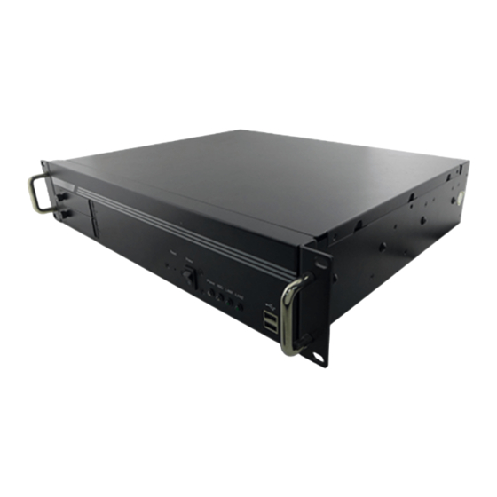
Page 17: Appearance And Dimensions
USER MANUAL CHAPTER 1 INTRODUCTION 1.5 Appearance and Dimensions This section includes front and rear side I/O ports location of the IH7T-RK2U Embedded Server Computer. All dimensions are shown in mm (millimeters). - 15 -... - Page 18 USER MANUAL CHAPTER 1 INTRODUCTION № № Description Description DC/AC Power Input with ① ⑪ Mic-in acrylic protection 3-pin terminal block ② ⑫ Power Switch GPS Antenna (Optional) ③ ⑬ PS/2 For Keyboard & Mouse PCI Slot (Optional) ④ ⑭ RS232 x 2 PCI Slot (Optional) RS-232/422/485 x 1...
-
Page 19: Led Status Indicators
USER MANUAL CHAPTER 1 INTRODUCTION 1.6 LED Status Indicators The IH7T-RK2U Embedded Server Computer provides LED indicators located on the front for status monitoring. LED Type Status Description System Power is On POWER System Power is Off Hard disk is being accessed... -
Page 20: Chapter 2: Hardware Installation
USER MANUAL CHAPTER 2 HARDWARE INSTALLATION HARDWARE INSTALLATION This chapter provides information on how to use external I/O and the installation of IH7T-RK2U Embedded Server Computer hardware. - 18 -... -
Page 21: Connectors
The following sections give you information about IH7T-RK2U standard connectors and pin assignments. 2.1.1 Power Connector The IH7T-RK2U DC/AC power source is a 3-pin terminal block connector with acrylic protection that supports 100-240V AC/ DC power input. The terminal is secured to the housing by screws. -
Page 22: Ps/2 For Keyboard & Mouse Connector
CHAPTER 2 HARDWARE INSTALLATION 2.1.2 PS/2 for Keyboard & Mouse Connector The IH7T-RK2U provides two PS/2 interfaces. The PS/2 connector supports Keyboard and Mouse. In other cases, especially in embedded applications, a mouse is not used. You can change BIOS settings when the mouse is not used. Go to BIOS standard setup menu and in the “Halt On”... -
Page 23: Vga Connector
2.1.4 VGA Connector The IH7T-RK2U uses standard 15pin D-sub connector. Plug 15-pin VGA signal cable to the VGA connector in the rear of motherboard, and plug the other end to the monitor. Secure cable connectors with hexagonal copper pillars M3x4mm. -
Page 24: Usb Connector
HARDWARE INSTALLATION 2.1.5 USB Connector The IH7T-RK2U provides four USB 3.0 connectors located on the rear and two USB 2.0 connectors on the front. Use USB connector to connect external devices such as mouse or keyboard to the box computer. -
Page 25: Line In, Line-Out, Mic-In Connector
USER MANUAL CHAPTER 2 HARDWARE INSTALLATION 2.1.7 Line in, Line-out, Mic-in Connector The audio jack of the IH7T-RK2U supports Audio 5.1 channel, and digital audio output. The audio interface includes Mic-in, line-in, and line-out. - 23 -... -
Page 26: Hardware Installation
USER MANUAL CHAPTER 2 HARDWARE INSTALLATION 2.2 Hardware Installation This chapter describes how to install hardware to the system. CAUTION/ ATTENTION Always remove the power cord before installing the hardware. 2.2.1 Removing the Top Cover Perform the following to open the equipment chassis for equipment installation: 1. -
Page 27: Pci Card Installation
USER MANUAL CHAPTER 2 HARDWARE INSTALLATION 2.2.2 PCI Card Installation Perform the following to install PCI Card: 1. First follow the instruction to remove the top cover. 2. Remove the PCI slot covers for the desired slot. 3. Insert the PCI card from the rear of the system through the opening, and push into the slot as shown below. -
Page 28: Memory Module Installation
USER MANUAL CHAPTER 2 HARDWARE INSTALLATION 2.2.3 Memory Module Installation The IH7T-RK2U provides two 204-pin SODIMM slot. The socket supports up to 16GB DDR3L 1600 SDRAM. To insert memory module: 1. Open the system chassis. 2. Locate the SODIMM slot on the motherboard. -
Page 29: Hard Disk Replacement
USER MANUAL CHAPTER 2 HARDWARE INSTALLATION 2.2.4 Hard Disk Replacement To replace hard disk: 1. Remove all power and signal connections. 2. Locate the removable hard drive bay in the front of the system. 3. Pull the hard drive mounting bracket out. 4. -
Page 30: External Antenna Installation
USER MANUAL CHAPTER 2 HARDWARE INSTALLATION 2.2.5 External Antenna Installation Notice that external GPS antenna is an optional feature of the IH7T-RK2U. To install external SMA antenna: 1. Remove the rubber cap on the SMA connector before installing the antenna. -
Page 31: Connecting The Power
2.3 Connecting the Power The DC power supply connector of the IH7T-RK2U embedded server computer is on the front panel. The DC power input for the IH7T-RK2U allows a voltage input range from 9 V DC to 30 V DC. -
Page 32: Chapter 3: Mounting
USER MANUAL CHAPTER 3 MOUNTING MOUNTING This chapter provides step-by-step mounting guide for all available mounting options. - 30 -... -
Page 33: Rack Mounting
MOUNTING CHAPTER 3: MOUNTING The IH7T-RK2U supports 2U rack mounting solution. 3.1 2U Rack Mounting Mounting Instruction: 1. Place the IH7T-RK2U on the 2U rack console, and fasten four screws at the front. 2. Connect all power cables. ❶ ❷... -
Page 34: Chapter 4: Ami Bios Setup
USER MANUAL CHAPTER 4 AMI BIOS SETUP AMI BIOS SETUP BIOS Setup Utility is a program for configuration basic Input / Output system settings of the computer for optimum use. This chapter provides information on how to use BIOS setup, its functions and menu. -
Page 35: How And When To Use Bios Setup
USER MANUAL CHAPTER 4 UEFI BIOS SETUP CHAPTER 4: AMI BIOS SETUP BIOS Setup Utility is a program for configuration basic Input / Output system settings of the computer for optimum use. This chapter provides information on how to use BIOS setup, its functions and menu. 4.1 How and When to Use BIOS Setup To enter the BIOS setup, you need to connect an external USB keyboard, external monitor and press Del key when the prompt appears on the screen... - Page 36 USER MANUAL CHAPTER 4 AMI BIOS SETUP The following Keys can be used after entering the BIOS Setup. Function General Help Previous Values Optimized Defaults Save & Exit Exit Change Opt. Enter Select or execute command Cursor ↑ Moves to the previous item Cursor ↓...
-
Page 37: Bios Functions
USER MANUAL CHAPTER 4 UEFI BIOS SETUP 4.2 BIOS Functions 4.2.1 Main Menu The Main menu displays the basic information about yoursystem including BIOS version, processor RC version, system language, time, and date. When you enter BIOS setup, the first menu that appears on the screen is the main menu.It contains the system information including BIOS version, processor RC version, system language, time, and date. -
Page 38: Advanced Settings
USER MANUAL CHAPTER 4 AMI BIOS SETUP 4.2.2 Advanced Settings Select the Advanced Tab from the setup menu to enter the advanced BIOS setup screen. You can select any of the items on the left frame of the screen to go to the sub menu for the item, such as CPU Configuration. - Page 39 USER MANUAL CHAPTER 4 UEFI BIOS SETUP BIOS Setting Description Setting Option Effect ACPI Settings Configures ACPI Enter Opens settings submenu RTC Wake Configures RTC Enter Opens Settings Wake parameters submenu Trusted Configures Enter Opens Computing Trusted submenu Computing parameters Configures CPU Enter Opens...
- Page 40 USER MANUAL CHAPTER 4 AMI BIOS SETUP 4.2.2.1 ACPI Settings Advanced Configuration and Power Interface (ACPI) settings allow to control how the power switch operates. The power supply can be adjusted for power requirements. You can use the screen to select options of ACPI configuration. A description of the selected items will appear on the right side of the screen.
- Page 41 USER MANUAL CHAPTER 4 UEFI BIOS SETUP 4.2.2.2 RTC Wake Settings BIOS Setting Description Setting Effect Option Enable or disable this function. When Wake system System wake on Enabled/ enabled, the system with Fixed Time alarm event Disabled will wake on the hr: min: sec specified.
- Page 42 USER MANUAL CHAPTER 4 AMI BIOS SETUP 4.2.2.3 Trusted Computing BIOS Setting Description Setting Option Effect Enable or disable Security Device Enabled/ Enable or disable BIOS support for Support Disabled this function. security device. Trusted Platform Enabled/ Enable or disable TPM State Module (TPM) Disabled...
- Page 43 USER MANUAL CHAPTER 4 UEFI BIOS SETUP 4.2.2.4 CPU Configuration Press <Enter> to view current CPU configuration and make settings for the following sub-items. BIOS Description Setting Effect Setting Option Reduces a computer EDB is a hardware-based system's, or a security component used server’s, vulnerability Enabled...
- Page 44 USER MANUAL CHAPTER 4 AMI BIOS SETUP frequency recommended by the manufacturer. Allows processor cores to run faster Turbo than the frequency recommended by the manufacturer. Enhanced Intel SpeedStep Technology gives your OS the ability to switch the Enabled/ Enable or disable this EIST processor's speed and Disabled...
- Page 45 USER MANUAL CHAPTER 4 UEFI BIOS SETUP 4.2.2.5 SATA Configuration BIOS Setting Description Setting Option Effect Allows users to SATA enable or disable Enabled/ Enable or disable Controller(s) the SATA Disabled this function controller(s). Allows users to Work in AHCI SATA Mode select mode of AHCI...
- Page 46 USER MANUAL CHAPTER 4 AMI BIOS SETUP 4.2.2.6 INTEL® Rapid Star Technology Allows users to enable or disable Intel rapid start technology. - 44 -...
- Page 47 USER MANUAL CHAPTER 4 UEFI BIOS SETUP BIOS Setting Description Setting Option Effect The system automatically Entry on S3 RTC wakes up and set Enable or disable Enabled/ Disabled Wake to Rapid Start this function Technology S3 mode. The time ranges Allows you to set Set parameters of from 0 minute...
- Page 48 USER MANUAL CHAPTER 4 AMI BIOS SETUP 4.2.2.7 PCH-FW Configuration This menu allows checking which FW Version, Mode, Type and SKU installed on your computer. - 46 -...
- Page 49 USER MANUAL CHAPTER 4 UEFI BIOS SETUP 4.2.2.8 Intel AMT Configuration - 47 -...
- Page 50 USER MANUAL CHAPTER 4 AMI BIOS SETUP BIOS Setting Description Setting Option Effect Set parameters of Enabled/ Intel ®Active Disabled. Enable or disable Intel AMT management this function Technology BIOS Default: Enabled Extension. Use this item to BIOS Hotkey BIOS Hotkey Enabled/ enable/disable Pressed...
- Page 51 USER MANUAL CHAPTER 4 UEFI BIOS SETUP 4.2.2.9 USB Configuration - 49 -...
- Page 52 USER MANUAL CHAPTER 4 AMI BIOS SETUP BIOS Setting Description Setting Effect Option Auto Disable legacy support if no USB devices are connected Legacy USB User can enable or Disable Will keep USB Support disable USB port. devices available only for EFI applications.
- Page 53 USER MANUAL CHAPTER 4 UEFI BIOS SETUP 4.2.2.10 F81866 H/W Monitor BIOS Setting Description Setting Option Effect Enable or Smart Fan Set parameters of Enabled/ disable this Function smart fan function Disabled function CPU Smart Fan Mode is responsible Possible for selecting the Setting Select the type...
- Page 54 USER MANUAL CHAPTER 4 AMI BIOS SETUP 4.2.2.11 Super IO Configuration BIOS Setting Description Setting Effect Option Set Parameters of Serial Enabled/ Ports. User can Serial Port Disabled Enable or Enable/Disable the serial 1,2,3 ,4,5,6 disable Serial port and select optimal Configuration Default: Port (COM)
-
Page 55: Chipset Menu
USER MANUAL CHAPTER 4 UEFI BIOS SETUP 4.2.3 Chipset Menu BIOS Setting Description Setting Option Effect PCH-IO PCH Parameters Enter Opens submenu Configuration System Agent System Agent (SA) Enter Opens submenu (SA) Parameters Configuration - 53 -... - Page 56 USER MANUAL CHAPTER 4 AMI BIOS SETUP 4.2.3.1 PCI –IO Configuration BIOS Setting Description Setting Option Effect PCI Express PCI Express Enter Opens submenu Configuration Parameters USB parameters Enter Opens submenu Configuration - 54 -...
- Page 57 USER MANUAL CHAPTER 4 UEFI BIOS SETUP 4.2.3.1.1 PCI Express Configuration BIOS Setting Description Setting Option Effect The control of Active State Power DMI Link ASPM Enable or disable Management on Enabled/ Disabled Control this function both NB side and SB side of the DMI Line DMI Link...
- Page 58 USER MANUAL CHAPTER 4 AMI BIOS SETUP 4.2.3.1.2 USB Configuration BIOS Setting Description Setting Option Effect Allows user to Enabled/ Enable or disable USB Precondition enable or disable Disabled this function USB Precondition Allows user to Smart Auto, Enabled/ XHCI Mode enable or disable Enabled/ Disabled...
- Page 59 USER MANUAL CHAPTER 4 UEFI BIOS SETUP 4.2.3.1.3 System Agent (SA) Configuration VT-d Allows users to enable or disable Intel Virtualization Technology for Directed I/O. - 57 -...
- Page 60 USER MANUAL CHAPTER 4 AMI BIOS SETUP 4.2.3.1.4 Graphics Configuration BIOS Setting Description Setting Effect Option Graphics Allows users to select Set Turbo IMON Turbo IMON which Graphics Turbo Current Current IMON Current. parameter Primary Allows users to select [IGFX], [Auto] Select Primary Display Primary Display...
- Page 61 USER MANUAL CHAPTER 4 UEFI BIOS SETUP 4.2.3.1.5 NB PCIe Configuration - 59 -...
-
Page 62: Boot Menu
USER MANUAL CHAPTER 4 AMI BIOS SETUP 4.2.4 Boot Menu The Boot menu sets the sequence of the devices to be searched for the operating system. The bootable devices will be automatically detected during POST and shown here, allowing you to set the sequence that the BIOS use to look for a boot device from which to load the operating system. - Page 63 USER MANUAL CHAPTER 4 UEFI BIOS SETUP BIOS Setting Description Setting Option Effect Setup Prompt Allows user to Enter Set the prompt Timeout configure the timeout number of seconds to stay in BIOS setup prompt screen. Boot NumLock Enables or Remains On State disables...
-
Page 64: Security Menu
USER MANUAL CHAPTER 4 AMI BIOS SETUP 4.2.5 Security Menu This section allows you to configure and improve your system and allows you to set up some system features according to your preference. BIOS Setting Description Setting Option Effect Administrator Displays whether Enter Enter password... -
Page 65: Save & Exit
USER MANUAL CHAPTER 4 UEFI BIOS SETUP 4.2.6 Save & Exit - 63 -... - Page 66 USER MANUAL CHAPTER 4 AMI BIOS SETUP BIOS Setting Description Setting Effect Option Save Changes This saves the changes to <YES> Save changes and Exit the CMOS and exits the BIOS Setup program. Discard This exits the BIOS Setup <YES> Saves the changes Changes and without saving the changes...
-
Page 67: Using Recovery Wizard To Restore Computer
USER MANUAL CHAPTER 4 UEFI BIOS SETUP 4.3 Using Recovery Wizard to Restore Computer Note: Before starting the recovery process, make sure to backup all user data. The data will be lost after the recovery process. To enable quick one-key recovery procedure: 1. -
Page 68: Watchdog Timer
To enable Watchdog, you need to download Winmate Watchdog utility. Find more information on Watchdog in “Watchdog Guide” that you can download from Winmate Download Center or File Share. Refer to the User Manual for more details. To enable watchdog in Watchdog AP follow the instructions below: 1. - Page 69 USER MANUAL CHAPTER 4 UEFI BIOS SETUP 3. In Watchdog utility window set countdown time and periodically feed time, or disable watchdog. Example: Every 10 min watchdog will monitor the system, in case any error occurs the system will restart automatically when the countdown time reaches 0.
-
Page 70: Watchdog Timer Behavior
USER MANUAL CHAPTER 4 AMI BIOS SETUP 4.4.1 Watchdog Timer Behavior The Advanced Configuration and Power Interface (ACPI) specification provides open standard for device configuration and power management by the operating system. Refer to the table below to check the description of different state: ACPI State Descriptions ACPI Power State... -
Page 71: Chapter 5: Driver Installation
USER MANUAL CHAPTER 5 DRIVER INSTALLATION DRIVER INSTALLATION This chapter provides instructions on how to install drivers on the IH7T- RK2U Embedded Server Computer. - 69 -... -
Page 72: Chipset Driver Installation
USER MANUAL CHAPTER 5 DRIVER INSTALLATION CHAPTER 5: DRIVER INSTALLATION This chapter provides instructions on how to install drivers on the IH7T-RK2U Embedded Server Computer. Notice that pictures in this example are for Windows 10 OS. 5.1 Chipset Driver Installation To install Chipset driver: 1. - Page 73 USER MANUAL CHAPTER 5 DRIVER INSTALLATION 3. Click Yes to agree to the license terms. 4. Check installation details and click Next. - 71 -...
- Page 74 USER MANUAL CHAPTER 5 DRIVER INSTALLATION 5. Click Next. 6. The installation is complete, click “Yes, I want to restart this computer now” to restart the system and exit installation window. - 72 -...
-
Page 75: Graphic Driver Installation
USER MANUAL CHAPTER 5 DRIVER INSTALLATION 5.2 Graphic Driver Installation To install Graphic driver: 1. Open the driver CD and double-click on Graphic driver. 2. Click “setup” to execute the setup. - 73 -... - Page 76 USER MANUAL CHAPTER 5 DRIVER INSTALLATION 3. Click Next to continue. 4. Click Accept to agree to the license terms. - 74 -...
- Page 77 USER MANUAL CHAPTER 5 DRIVER INSTALLATION 5. Check installation details and click Next. 6. Click Next. - 75 -...
- Page 78 USER MANUAL CHAPTER 5 DRIVER INSTALLATION 7. . The installation is complete, click “Yes, I want to restart this computer now”, and click Finish to restart the system and exit installation window. - 76 -...
-
Page 79: Audio Driver Installation
USER MANUAL CHAPTER 5 DRIVER INSTALLATION 5.3 Audio Driver Installation To install Audio driver: 1. Open the driver CD and open the file document “alc655_driver” and click on “Vista_Win7_R260.exe” to execute the setup. 2. Click Yes to install driver. 3. Click Yes, I want to restart my computer now to continue installation. - 77 -... -
Page 80: Ethernet Driver Installation
USER MANUAL CHAPTER 5 DRIVER INSTALLATION 5.4 Ethernet Driver Installation To install Ethernet driver: 1. Right-click the desktop, and then click Properties. 2. In the Other device dialog box, click the Settings tab. - 78 -... - Page 81 USER MANUAL CHAPTER 5 DRIVER INSTALLATION 3. Click “Update Driver” to execute the setup. 4. Click “Browse my computer for driver software“ to install driver. - 79 -...
- Page 82 USER MANUAL CHAPTER 5 DRIVER INSTALLATION 5. Choose the path to install driver. 6. Click “Close“ to exit installation window. - 80 -...
-
Page 83: Com Port Driver Installation
USER MANUAL CHAPTER 5 DRIVER INSTALLATION 5.5 COM Port Driver Installation To install COM Port driver: 1. If the system is WIN7 please first do close UAC (Refer following “Disabling User Account Control (UAC) in Windows 7”). 2. Extract the Patch_0408.zip to a folder. 3. - Page 84 USER MANUAL CHAPTER 5 DRIVER INSTALLATION 5. You will need to restart your computer for driver install success. Type in this command from the Run menu: C:\Windows\System32\UserAccountControlSettings.exe Or UAC. To turn off UAC, move the slider to the Never notify position, and then click OK. If you're prompted for an administrator password or confirmation, type the password or provide confirmation.
-
Page 85: Chapter 6: Technical Support
USER MANUAL CHAPTER 6 TECHNICAL SUPPORT TECHNICAL SUPPORT This chapter includes pathway for technical support and Software Development Kit (SDK). - 83 -... -
Page 86: Software Developer Support
6.1 Software Developer Support You can download SDK, derivers and other document from Winmate Download Center. Winmate Download Center http://www.winmate.com/ > Support > Download Center > Embedded Computing > IH7T-RK2U 6.2 Problem Report Form Embedded Server Computer... -
Page 87: Appendix A: Ordering Information
USER MANUAL APPENDIX A ORDERING INFORMATION ORDERING INFORMATION This section includes IH7T-RK2U Embedded Server Computer ordering information. Appendix - 85 -... - Page 88 USER MANUAL APPENDIX A ORDERING INFORMATION APPENDIX A: ORDERING INFORMATION IH7T-RK2U Embedded Server Computer available in the following configurations: Item Specifications Option : 2 x 2.5" SATAIII HDD (up to 1TB) * or Storage 2 x 2.5" SATAIII SSD (up to 512GB) * 1 x mSATA SSD 128GB (up to 256GB) Two 2.5”...
- Page 89 NOTES _______________________________________________________ _______________________________________________________ _______________________________________________________ _______________________________________________________ _______________________________________________________ _______________________________________________________ _______________________________________________________ _______________________________________________________ _______________________________________________________ _______________________________________________________ _______________________________________________________ _______________________________________________________ _______________________________________________________ _______________________________________________________ _______________________________________________________ _______________________________________________________ _______________________________________________________ _______________________________________________________ _______________________________________________________ _______________________________________________________...
- Page 90 NOTES _______________________________________________________ _______________________________________________________ _______________________________________________________ _______________________________________________________ _______________________________________________________ _______________________________________________________ _______________________________________________________ _______________________________________________________ _______________________________________________________ _______________________________________________________ _______________________________________________________ _______________________________________________________ _______________________________________________________ _______________________________________________________ _______________________________________________________ _______________________________________________________ _______________________________________________________ _______________________________________________________ _______________________________________________________ _______________________________________________________...
- Page 92 Winmate Inc. 9F, No.111-6, Shing-De Rd., San-Chung District, New Taipei City 24158, Taiwan, R.O.C Tel: 886-2-8511-0288 Fax: 886-2-8511-0211 Email: sales@winmate.com.tw Official website: www.winmate.com...
Need help?
Do you have a question about the IH7T-RK2U and is the answer not in the manual?
Questions and answers