TR-Electronic LE-25 Assembly Instructions Manual
Hide thumbs
Also See for LE-25:
- Assembly instructions manual (172 pages) ,
- User manual (91 pages) ,
- User manual (55 pages)
Table of Contents
Advertisement
Available languages
Available languages
Quick Links
Gesamtbedienungsanleitung
Für
LE-25 SSI 25M
Material Nr.
2600-00002
Generiert am
12.07.2023
Enthält Originalbedienungsanleitung
Dokumentationsabschnitte
Montageanleitung de/en LE-25/LE-200 Montageanleitung
Betriebsanleitung
de/en LE-25 SSI
Konformitätserklärung de/en LE-25, LE-100, LE-200 Baureihe
Technische Daten
Seite 1/1
TR-ELE-BA-DGB-0018-07.pdf
TR-ELE-BA-DGB-0026-02.pdf
TR-ELE-KE-DGB-0010-05.pdf
Änderungen vorbehalten.
TR-Electronic GmbH
Eglishalde 6
78647 Trossingen
Tel. +49 (0) 7425 228-0
info@tr-electronic.de
www.tr-electronic.de
Advertisement
Chapters
Table of Contents

Subscribe to Our Youtube Channel
Related Manuals for TR-Electronic LE-25


Summary of Contents for TR-Electronic LE-25
- Page 1 Generiert am 12.07.2023 Enthält Originalbedienungsanleitung Dokumentationsabschnitte Montageanleitung de/en LE-25/LE-200 Montageanleitung TR-ELE-BA-DGB-0018-07.pdf Betriebsanleitung de/en LE-25 SSI TR-ELE-BA-DGB-0026-02.pdf Konformitätserklärung de/en LE-25, LE-100, LE-200 Baureihe TR-ELE-KE-DGB-0010-05.pdf Technische Daten Änderungen vorbehalten. TR-Electronic GmbH Eglishalde 6 78647 Trossingen Tel. +49 (0) 7425 228-0 Seite 1/1 info@tr-electronic.de...
- Page 2 Seite 2 - 26 Page 27 - 52 Laser-Entfernungs-Messgerät LE-25 LE-200 Abbildungen ähnlich _Grundlegende Sicherheitshinweise _Verwendungszweck _Allgemeine Funktionsbeschreibung _Montagehinweise Montageanleitung...
- Page 3 Menüauswahlen von Software. < > weist auf Tasten der Tastatur Ihres Computers hin (wie etwa <RETURN>). TR-Electronic GmbH 2010, All Rights Reserved Printed in the Federal Republic of Germany Page 2 of 52 TR - ELE - BA - DGB - 0018 - 07...
-
Page 4: Table Of Contents
7 Zubehör ............................25 7.1 Artikel ............................25 7.2 Schnittstellen-spezifische Benutzerhandbücher ..............25 7.3 Steckerbelegungen ......................... 26 TR-Electronic GmbH 2010, All Rights Reserved Printed in the Federal Republic of Germany 06/14/2019 TR - ELE - BA - DGB - 0018 - 07... -
Page 5: Änderungs-Index
12.06.17 LE-300 entfernt, LE-25 hinzugefügt Ergänzungen für LE-25 mit Feldbus-Schnittstelle 14.06.19 TR-Electronic GmbH 2010, All Rights Reserved Printed in the Federal Republic of Germany Page 4 of 52 TR - ELE - BA - DGB - 0018 - 07... -
Page 6: Allgemeines
Steckerbelegung schnittstellenspezifisches Benutzerhandbuch, siehe Kapitel „Zubehör“ Produktdatenblatt: www.tr-electronic.de/s/S013160 TR-Electronic GmbH 2010, All Rights Reserved Printed in the Federal Republic of Germany 06/14/2019 TR - ELE - BA - DGB - 0018 - 07 Page 5 of 52... -
Page 7: Eu-Konformitätserklärung
Allgemeines 1.3 EU-Konformitätserklärung Die Mess-Systeme wurden unter Beachtung geltender europäischer bzw. internationaler Normen und Richtlinien entwickelt, konstruiert und gefertigt. Eine entsprechende Konformitätserklärung kann bei der Firma TR-Electronic GmbH angefordert werden. Hersteller Produkte, TR-Electronic GmbH D-78647 Trossingen, besitzt ein zertifiziertes Qualitätssicherungssystem gemäß ISO 9001. -
Page 8: Allgemeine Funktionsbeschreibung
Reflexfolie d = f( ) Abbildung 1: Funktionsprinzip Abbildung 2: Messbereich TR-Electronic GmbH 2010, All Rights Reserved Printed in the Federal Republic of Germany 06/14/2019 TR - ELE - BA - DGB - 0018 - 07 Page 7 of 52... -
Page 9: Grundlegende Sicherheitshinweise
Anlage/Maschine in die das Mess-System eingebaut werden soll, den Bestimmungen der EU-EMV-Richtlinie, den harmonisierten Normen, Europanormen oder den entsprechenden nationalen Normen entspricht. TR-Electronic GmbH 2010, All Rights Reserved Printed in the Federal Republic of Germany Page 8 of 52... -
Page 10: Allgemeine Gefahren Bei Der Verwendung Des Produkts
das Beachten beigefügter Dokumente, das Betreiben des Mess-Systems innerhalb der in den technischen Daten angegebenen Grenzwerten, siehe Produktdatenblatt. TR-Electronic GmbH 2010, All Rights Reserved Printed in the Federal Republic of Germany 06/14/2019 TR - ELE - BA - DGB - 0018 - 07... -
Page 11: Bestimmungswidrige Verwendung
Eigenmächtige durchgeführte Reparaturen. Katastrophenfälle durch Fremdeinwirkung und höhere Gewalt. TR-Electronic GmbH 2010, All Rights Reserved Printed in the Federal Republic of Germany Page 10 of 52 TR - ELE - BA - DGB - 0018 - 07... -
Page 12: Organisatorische Maßnahmen
Montage, Installation, Inbetriebnahme und Bedienung festlegen. Beaufsichtigungspflicht bei zu schulendem oder anzulernendem Personal ! TR-Electronic GmbH 2010, All Rights Reserved Printed in the Federal Republic of Germany 06/14/2019 TR - ELE - BA - DGB - 0018 - 07... -
Page 13: Sicherheitstechnische Hinweise
Nutzentfernung durch eine diffus reflektierende Zielfläche so zu begrenzen, dass eine Gefährdung durch direkte oder diffuse Reflexion möglichst gering ist. Hierzu sollte die bei dem Mess-System beigestellte Reflexionsfolie von der Firma TR-Electronic verwendet werden. Soweit möglich sollte der unabgeschirmte Laserstrahl außerhalb des Arbeits- und Verkehrsbereiches in einem möglichst kleinen, nicht... - Page 14 Produktdatenblatt Laserwarnschild Das Laserwarnschild befindet sich an Position Abbildung 4: Laserwarnschild TR-Electronic GmbH 2010, All Rights Reserved Printed in the Federal Republic of Germany 06/14/2019 TR - ELE - BA - DGB - 0018 - 07 Page 13 of 52...
- Page 15 Linsenöffnung des Mess-Systems sowie Reflektorfolie regelmäßig mit einem weichen Tuch reinigen. Zur Reinigung keine aggressiven Reinigungsmittel wie Verdünner oder Aceton verwenden! TR-Electronic GmbH 2010, All Rights Reserved Printed in the Federal Republic of Germany Page 14 of 52 TR - ELE - BA - DGB - 0018 - 07...
-
Page 16: Transport / Lagerung
Unsachgemäßes Verpackungsmaterial kann beim Transport Schäden am Gerät verursachen. Lagerung Lagertemperatur: siehe Produktdatenblatt Trocken lagern TR-Electronic GmbH 2010, All Rights Reserved Printed in the Federal Republic of Germany 06/14/2019 TR - ELE - BA - DGB - 0018 - 07 Page 15 of 52... -
Page 17: Neuer Reflektor
Mess-Systeme mit diesem Label dürfen nur mit dem beigefügten Reflektor betrieben werden. Vorhandene Reflektoren sind zu entfernen. Vorzugsrichtung TR-Electronic GmbH 2010, All Rights Reserved Printed in the Federal Republic of Germany Page 16 of 52 TR - ELE - BA - DGB - 0018 - 07... -
Page 18: Montagehinweise / Schema
Reflexionsfolien anderer Hersteller sollten grundsätzlich nicht eingesetzt werden, da sich alle Angaben im Kapitel "Technische Daten" im schnittstellenspezifischen Benutzerhandbuch auf die dem Gerät beigestellte Reflexionsfolie beziehen. TR-Electronic GmbH 2010, All Rights Reserved Printed in the Federal Republic of Germany 06/14/2019... - Page 19 Blatt-Papier mit einem ca. 2cm großem Loch im Zent- Abbildung 7: Wegleitung der Oberflächenreflektion TR-Electronic GmbH 2010, All Rights Reserved Printed in the Federal Republic of Germany Page 18 of 52 TR - ELE - BA - DGB - 0018 - 07...
-
Page 20: Parallelbetrieb Von Laserstrecken
Die Ausrichtung erfolgt wie unter Kapitel 5 / 5.1 beschrieben. Abbildung 8: Mindestabstand im Parallelbetrieb TR-Electronic GmbH 2010, All Rights Reserved Printed in the Federal Republic of Germany 06/14/2019 TR - ELE - BA - DGB - 0018 - 07... -
Page 21: Maßzeichnungen
Maßzeichnungen 6 Maßzeichnungen 6.1 LE-25 6.1.1 SSI TR-Electronic GmbH 2010, All Rights Reserved Printed in the Federal Republic of Germany Page 20 of 52 TR - ELE - BA - DGB - 0018 - 07 06/14/2019... -
Page 22: Feldbus
6.1.2 Feldbus TR-Electronic GmbH 2010, All Rights Reserved Printed in the Federal Republic of Germany 06/14/2019 TR - ELE - BA - DGB - 0018 - 07 Page 21 of 52... -
Page 23: Kabelverschraubungen
Maßzeichnungen 6.2 LE-200 6.2.1 Kabelverschraubungen TR-Electronic GmbH 2010, All Rights Reserved Printed in the Federal Republic of Germany Page 22 of 52 TR - ELE - BA - DGB - 0018 - 07 06/14/2019... -
Page 24: Stecker
6.2.2 Stecker TR-Electronic GmbH 2010, All Rights Reserved Printed in the Federal Republic of Germany 06/14/2019 TR - ELE - BA - DGB - 0018 - 07 Page 23 of 52... -
Page 25: 12-Pol. Contact
Maßzeichnungen 6.2.3 12-pol. Contact TR-Electronic GmbH 2010, All Rights Reserved Printed in the Federal Republic of Germany Page 24 of 52 TR - ELE - BA - DGB - 0018 - 07 06/14/2019... -
Page 26: Zubehör
LE-200 Profinet IO Betriebsanleitungen: Drehgeber und Lineargeber - Internet Download: www.tr-electronic.de/service/downloads/betriebsanleitungen/drehgeber-und- lineargeber.html TR-Electronic GmbH 2010, All Rights Reserved Printed in the Federal Republic of Germany 06/14/2019 TR - ELE - BA - DGB - 0018 - 07 Page 25 of 52... -
Page 27: Steckerbelegungen
LE-200 CANopen 2 x M12-Stecker TR-ELE-TI-DGB-0020 LE-200 Profinet IO Steckerbelegungen - Internet Download: www.tr-electronic.de/service/downloads/steckerbelegungen.html?L=0 TR-Electronic GmbH 2010, All Rights Reserved Printed in the Federal Republic of Germany Page 26 of 52 TR - ELE - BA - DGB - 0018 - 07 06/14/2019... - Page 28 _Intended use _General functional description Assembly Instructions _Instructions for mounting TR-Electronic GmbH 2010, All Rights Reserved Printed in the Federal Republic of Germany 06/14/2019 TR - ELE - BA - DGB - 0018 - 07 Page 27 of 52...
- Page 29 < > indicates keys on your computer keyboard (such as <RETURN>). TR-Electronic GmbH 2010, All Rights Reserved Printed in the Federal Republic of Germany Page 28 of 52 TR - ELE - BA - DGB - 0018 - 07...
- Page 30 7.1 Products ..........................51 7.2 Interface-specific User Manuals ..................... 51 7.3 Pin assignments ........................52 TR-Electronic GmbH 2010, All Rights Reserved Printed in the Federal Republic of Germany 06/14/2019 TR - ELE - BA - DGB - 0018 - 07...
-
Page 31: Revision Index
Mechanical characteristics removed -> reference to the product data sheets 02/01/17 Other applicable documents LE-300 removed, LE-25 added 06/12/17 Additions for LE-25 with fieldbus interface 06/14/19 TR-Electronic GmbH 2010, All Rights Reserved Printed in the Federal Republic of Germany Page 30 of 52... -
Page 32: General Information
User Manual, see chapter “Accessories” Product data sheet: www.tr-electronic.com/s/S013161 TR-Electronic GmbH 2010, All Rights Reserved Printed in the Federal Republic of Germany 06/14/2019 TR - ELE - BA - DGB - 0018 - 07 Page 31 of 52... -
Page 33: Eu Declaration Of Conformity
1.3 EU Declaration of conformity The measuring systems have been developed, designed and manufactured under observation of the applicable international and European standards and directives. A corresponding declaration of conformity can be requested from TR-Electronic GmbH. The manufacturer of the product, TR-Electronic GmbH in D-78647 Trossingen, operates a certified quality assurance system in accordance with ISO 9001. -
Page 34: General Functional Description
Reflecting foil d = f( ) Figure 1: Function principle Figure 2: Measuring range TR-Electronic GmbH 2010, All Rights Reserved Printed in the Federal Republic of Germany 06/14/2019 TR - ELE - BA - DGB - 0018 - 07... -
Page 35: Basic Safety Instructions
EU EMC Directive, the harmonized standards, European standards or the corresponding national standards. TR-Electronic GmbH 2010, All Rights Reserved Printed in the Federal Republic of Germany Page 34 of 52... -
Page 36: General Risks When Using The Product
observing the enclosed documents, operating the measuring system within the limit values specified in the technical data, see Product Data Sheet TR-Electronic GmbH 2010, All Rights Reserved Printed in the Federal Republic of Germany 06/14/2019 TR - ELE - BA - DGB - 0018 - 07... -
Page 37: Non-Intended Use
Repairs carried out autonomously. Third party interference and Acts of God. TR-Electronic GmbH 2010, All Rights Reserved Printed in the Federal Republic of Germany Page 36 of 52 TR - ELE - BA - DGB - 0018 - 07... -
Page 38: Organizational Measures
Verlag GmbH). Define clear rules of responsibilities for the assembly, installation, start-up and operation. The obligation exists to provide supervision for trainee personnel ! TR-Electronic GmbH 2010, All Rights Reserved Printed in the Federal Republic of Germany 06/14/2019... -
Page 39: Safety Information's
For this purpose, you should use the TR-Electronic reflecting foil supplied with the measuring system. The area outside the operating range where the unshielded laser beam falls should be limited as far as possible and should remain out of bounds, particularly in the area above and below eye level. - Page 40 Laser warning symbol The laser warning symbol is located at position Figure 4: Laser warning symbol TR-Electronic GmbH 2010, All Rights Reserved Printed in the Federal Republic of Germany 06/14/2019 TR - ELE - BA - DGB - 0018 - 07...
- Page 41 Clean the lens opening of the measuring system and the reflector foil regularly with a damp cloth. Do not use any aggressive detergents, such as thinners or acetone! TR-Electronic GmbH 2010, All Rights Reserved Printed in the Federal Republic of Germany Page 40 of 52...
-
Page 42: Transportation / Storage
The wrong packaging material can cause damage to the device during transportation. Storage Storage temperature: see product data sheet Store in a dry place TR-Electronic GmbH 2010, All Rights Reserved Printed in the Federal Republic of Germany 06/14/2019 TR - ELE - BA - DGB - 0018 - 07... -
Page 43: New Reflector
Measuring systems with this label must be operated with the enclosed reflector only. Present reflectors must be removed. Preferred direction TR-Electronic GmbH 2010, All Rights Reserved Printed in the Federal Republic of Germany Page 42 of 52 TR - ELE - BA - DGB - 0018 - 07... -
Page 44: Instructions For Mounting / Schematic
Reflecting foils by other manufacturers should not be used under any circumstances, as all the information in the interface-specific User Manual in the "Technical data" chapter refers to the foil already supplied with the device. TR-Electronic GmbH 2010, All Rights Reserved Printed in the Federal Republic of Germany 06/14/2019... - Page 45 Paper with an approx. 2 cm large hole in the center Figure 7: Transmitting away the surface reflectivity TR-Electronic GmbH 2010, All Rights Reserved Printed in the Federal Republic of Germany Page 44 of 52 TR - ELE - BA - DGB - 0018 - 07...
-
Page 46: Parallel Operation Of Laser Linear Paths
(see arrows) points not into the other laser linear path. The alignment is carried out as described in chapter 5 / 5.1. Figure 8: Minimum distance in parallel operation TR-Electronic GmbH 2010, All Rights Reserved Printed in the Federal Republic of Germany 06/14/2019... -
Page 47: Dimension Drawings
Dimension drawings 6 Dimension drawings 6.1 LE-25 6.1.1 SSI TR-Electronic GmbH 2010, All Rights Reserved Printed in the Federal Republic of Germany Page 46 of 52 TR - ELE - BA - DGB - 0018 - 07 06/14/2019... -
Page 48: Fieldbus Interface
6.1.2 Fieldbus Interface TR-Electronic GmbH 2010, All Rights Reserved Printed in the Federal Republic of Germany 06/14/2019 TR - ELE - BA - DGB - 0018 - 07 Page 47 of 52... -
Page 49: Type With Cable Glands
Dimension drawings 6.2 LE-200 6.2.1 Type with cable glands TR-Electronic GmbH 2010, All Rights Reserved Printed in the Federal Republic of Germany Page 48 of 52 TR - ELE - BA - DGB - 0018 - 07 06/14/2019... -
Page 50: Type With Connectors
6.2.2 Type with connectors TR-Electronic GmbH 2010, All Rights Reserved Printed in the Federal Republic of Germany 06/14/2019 TR - ELE - BA - DGB - 0018 - 07 Page 49 of 52... -
Page 51: Type With 12-Pole Contact
Dimension drawings 6.2.3 Type with 12-pole Contact TR-Electronic GmbH 2010, All Rights Reserved Printed in the Federal Republic of Germany Page 50 of 52 TR - ELE - BA - DGB - 0018 - 07 06/14/2019... -
Page 52: Accessories
LE-200 Profinet IO Operating Manuals: Encoder and Linear Transducer - Internet Download: www.tr-electronic.com/service/downloads/operating-manuals/encoder-and-linear- transducer.html TR-Electronic GmbH 2010, All Rights Reserved Printed in the Federal Republic of Germany 06/14/2019 TR - ELE - BA - DGB - 0018 - 07... -
Page 53: Pin Assignments
TR-ELE-TI-DGB-0020 LE-200 Profinet IO Pin Assignments - Internet Download: www.tr-electronic.com/service/downloads/steckerbelegungen.html?L=0 TR-Electronic GmbH 2010, All Rights Reserved Printed in the Federal Republic of Germany Page 52 of 52 TR - ELE - BA - DGB - 0018 - 07 06/14/2019... - Page 54 Seite 2 - 24 Page 25 - 47 Laser-Entfernungs-Messgerät LE-25 Abbildung ähnlich _Zusätzliche Sicherheitshinweise _Installation _Inbetriebnahme _Parametrierung _Fehlerursachen und Abhilfen Benutzerhandbuch Schnittstelle...
- Page 55 Courier-Schrift zeigt Text an, der auf dem Display bzw. Bildschirm sichtbar ist und Menüauswahlen von Software. < > weist auf Tasten der Tastatur Ihres Computers hin (wie etwa <RETURN>). TR-Electronic GmbH 2017, All Rights Reserved Printed in the Federal Republic of Germany Page 2 of 48 TR-ELE-BA-DGB-0026 v02 01/31/2022...
- Page 56 5.3.3 Fehlerquittierung ..................... 17 5.3.4 Ausgabewert bei Fehler ..................17 5.3.5 Warnbit Temperatur ab ................... 18 5.3.6 Warnbit Intensität unter ................... 18 TR-Electronic GmbH 2017, All Rights Reserved Printed in the Federal Republic of Germany 01/31/2022 TR-ELE-BA-DGB-0026 v02 Page 3 of 48...
-
Page 57: Inhaltsverzeichnis
5.6.4 Vorzeichen ......................22 6 Fehlerursachen und Abhilfen ......................23 6.1 Optische Anzeigen ........................23 6.2 Fehlercodes ..........................24 TR-Electronic GmbH 2017, All Rights Reserved Printed in the Federal Republic of Germany Page 4 of 48 TR-ELE-BA-DGB-0026 v02 01/31/2022... -
Page 58: Änderungs-Index
Änderungs-Index Änderung Datum Index Erstausgabe 08.06.2017 Anpassungen an aktuelle Hardware-Version 15.06.2020 Kapitel „Kabelspezifikation“ entfernt 31.01.2022 TR-Electronic GmbH 2017, All Rights Reserved Printed in the Federal Republic of Germany 01/31/2022 TR-ELE-BA-DGB-0026 v02 Page 5 of 48... -
Page 59: Allgemeines
Bestandteil einer Anlage. Es gelten somit zusammen folgende Dokumentationen: siehe Kapitel „Mitgeltende Dokumente“ in der Montageanleitung www.tr-electronic.de/f/TR-ELE-BA-DGB-0018 Produktdatenblätter www.tr-electronic.de/s/S015494 TR-Electronic GmbH 2017, All Rights Reserved Printed in the Federal Republic of Germany Page 6 of 48 TR-ELE-BA-DGB-0026 v02 01/31/2022... -
Page 60: Verwendete Abkürzungen / Begriffe
Synchron-Serielles-Interface Least Significant Bit (niederwertiges Bit) Most Significant Bit (höchstwertiges Bit) Periodendauer SSI Monozeit Pausenzeit Verzögerungszeit Vorzeichen Hexadezimale Darstellung TR-Electronic GmbH 2017, All Rights Reserved Printed in the Federal Republic of Germany 01/31/2022 TR-ELE-BA-DGB-0026 v02 Page 7 of 48... -
Page 61: Zusätzliche Sicherheitshinweise
Dies gilt in besonderem Maße für nur gelegentlich, z. B. bei der Parametrierung des Mess-Systems, tätig werdendes Personal. TR-Electronic GmbH 2017, All Rights Reserved Printed in the Federal Republic of Germany Page 8 of 48... -
Page 62: Ssi Informationen
Datenbits nach jeweils 26 Takten eines Büschels wiederholt werden. Von Nachteil ist aber die stark erhöhte Übertragungsdauer. Abbildung 1: SSI Prinzip-Eingangsschaltung Abbildung 2: SSI-Ausgangsschaltung TR-Electronic GmbH 2017, All Rights Reserved Printed in the Federal Republic of Germany 01/31/2022 TR-ELE-BA-DGB-0026 v02... -
Page 63: Installation / Inbetriebnahmevorbereitung
Richtlinie sowie die Schirmungs- und Erdungsrichtlinien in den jeweils gültigen Fassungen zu beachten. ● Es wird empfohlen, nach Abschluss der Montagearbeiten eine visuelle Abnahme mit Protokoll zu erstellen. TR-Electronic GmbH 2017, All Rights Reserved Printed in the Federal Republic of Germany Page 10 of 48 TR-ELE-BA-DGB-0026 v02 01/31/2022... -
Page 64: Anschluss
Beschreibung Kein Fehler vorhanden Mindestens ein Mess-System - Fehler aufgetreten Entsprechende Maßnahmen im Fehlerfall siehe Kapitel „Optische Anzeigen“, Seite 23. TR-Electronic GmbH 2017, All Rights Reserved Printed in the Federal Republic of Germany 01/31/2022 TR-ELE-BA-DGB-0026 v02 Page 11 of 48... -
Page 65: Anbindung An Den Pc (Programmierung)
TR-E-TI-DGB-0074, Deutsch/Englisch Für den Betrieb ab Windows 7 wird der USB PC-Adapter HID (V5), Art-Nr.: 490-00313 mit Installationsanleitung TR-E-TI-DGB-0103 benötigt. TR-Electronic GmbH 2017, All Rights Reserved Printed in the Federal Republic of Germany Page 12 of 48 TR-ELE-BA-DGB-0026 v02 01/31/2022... -
Page 66: Ssi Schnittstelle
übertragende Anzahl der Datenbits. Typische SSI-Übertragungssequenzen Takt+ Daten+ Monoflopzeit SSI-Übertragungsformat High Takt+ High Daten+ High intern retriggerbares Monoflop TR-Electronic GmbH 2017, All Rights Reserved Printed in the Federal Republic of Germany 01/31/2022 TR-ELE-BA-DGB-0026 v02 Page 13 of 48... -
Page 67: Parametrierung Über Trwinprog
Verzögerungen bei der Messwert-Berechnung zur Folge. Auswahl Default gering mittel hoch kein MAvg (Movement Average), Ausgabe des Rohwertes TR-Electronic GmbH 2017, All Rights Reserved Printed in the Federal Republic of Germany Page 14 of 48 TR-ELE-BA-DGB-0026 v02 01/31/2022... -
Page 68: Messwert-Ausgabe-Zeit
SSI-Schnittstelle. Ein eventuell definiertes Fehler-Bit ist darin nicht mit enthalten. Auswahl Beschreibung Default 12 Bit Anzahl SSI-Datenbits = 12 24 Bit 31 Bit Anzahl SSI-Datenbits = 31 TR-Electronic GmbH 2017, All Rights Reserved Printed in the Federal Republic of Germany 01/31/2022 TR-ELE-BA-DGB-0026 v02 Page 15 of 48... -
Page 69: Code
Positionswert an. TestWert1/2, Testposition, Diagnosezwecke Feinwert, Grobwert 5.2.5 SSI Mono-Zeit Untergrenze 20 µs Obergrenze 250 µs Default 20 µs TR-Electronic GmbH 2017, All Rights Reserved Printed in the Federal Republic of Germany Page 16 of 48 TR-ELE-BA-DGB-0026 v02 01/31/2022... -
Page 70: Fehlerbehandlung
Alle 24 Bit werden auf '1' gesetzt Position = -1 (0xFFFFFF oder -1) letzt. gült. Wert Es wird die letzte gültige Position ausgegeben TR-Electronic GmbH 2017, All Rights Reserved Printed in the Federal Republic of Germany 01/31/2022 TR-ELE-BA-DGB-0026 v02 Page 17 of 48... -
Page 71: Warnbit Temperatur Ab
Externer Schalteingang wird zur Abschaltung der Laser-Diode Laserdiode (LD) benutzt. Externer Schalteingang wird zur Rücksetzung Fehler rücksetzen eines auftretenden Fehlers benutzt. TR-Electronic GmbH 2017, All Rights Reserved Printed in the Federal Republic of Germany Page 18 of 48 TR-ELE-BA-DGB-0026 v02 01/31/2022... -
Page 72: Aktive Eingangs-Flanke
Festlegung des Positionswertes, auf welchen der Laser justiert wird, wenn die Presetfunktion ausgeführt wird (siehe "Funktion externer Eingang", Seite 18). Der Wert muss sich innerhalb des Messbereichs des Lasers befinden. Defaultwert = 0. TR-Electronic GmbH 2017, All Rights Reserved Printed in the Federal Republic of Germany 01/31/2022 TR-ELE-BA-DGB-0026 v02... -
Page 73: Istwerte
Das Bit wird gesetzt, wenn der Messbereich unter- bzw. Messbereich überschritten überschritten wird (< 0 m, > 25 m). Bit 7 TR-Electronic GmbH 2017, All Rights Reserved Printed in the Federal Republic of Germany Page 20 of 48 TR-ELE-BA-DGB-0026 v02... -
Page 74: Hardware-Info
Bit 3, Fehler Temperatur-Sensor Bit 4, Fehler FPGA Bit 5, Fehler Linearitäts-Tabelle Bit 6, Fehler Independent Watchdog Bit 7, Fehler Intensitäts-Tabelle TR-Electronic GmbH 2017, All Rights Reserved Printed in the Federal Republic of Germany 01/31/2022 TR-ELE-BA-DGB-0026 v02 Page 21 of 48... -
Page 75: Geschwindigkeit
Vorzeichen, oder ohne Vorzeichen ausgegeben werden soll. Auswahl Beschreibung Default kein Vorzeichen, Ausgabe ohne Vorzeichen immer positiv richtungsabhängiges Ausgabe als Betrag mit Vorzeichen Vorzeichen TR-Electronic GmbH 2017, All Rights Reserved Printed in the Federal Republic of Germany Page 22 of 48 TR-ELE-BA-DGB-0026 v02 01/31/2022... -
Page 76: Fehlerursachen Und Abhilfen
Mess-System ausgetauscht werden. Bit2 im Status = 1 Tritt der Fehler wiederholt auf, muss das Gerät ebenfalls getauscht werden. TR-Electronic GmbH 2017, All Rights Reserved Printed in the Federal Republic of Germany 01/31/2022 TR-ELE-BA-DGB-0026 v02 Page 23 of 48... -
Page 77: Fehlercodes
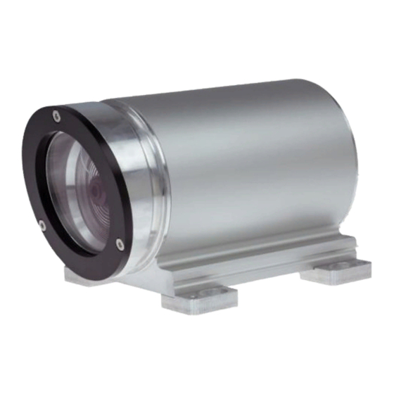
überschritten (< 0 m, > 25 m). gegeben. Um die statische Positionsausgabe überschritten zu verlassen, muss die Distanzmessung innerhalb des Messbereiches vorgenommen werden. TR-Electronic GmbH 2017, All Rights Reserved Printed in the Federal Republic of Germany Page 24 of 48 TR-ELE-BA-DGB-0026 v02 01/31/2022... - Page 78 Laser Measuring Device LE-25 Stock photo _Additional safety instructions User Manual _Installation Interface _Commissioning _Parameter setting _Causes of faults and remedies TR-Electronic GmbH 2017, All Rights Reserved Printed in the Federal Republic of Germany 01/31/2022 TR-ELE-BA-DGB-0026 v02 Page 25 of 48...
- Page 79 Courier font displays text, which is visible on the display or screen and software menu selections. < > indicates keys on your computer keyboard (such as <RETURN>). TR-Electronic GmbH 2017, All Rights Reserved Printed in the Federal Republic of Germany Page 26 of 48 TR-ELE-BA-DGB-0026 v02...
- Page 80 5.3.4 Position in case of a failure ..................41 5.3.5 Warning bit Temperature from ................42 5.3.6 Warning bit Intensity under ..................42 TR-Electronic GmbH 2017, All Rights Reserved Printed in the Federal Republic of Germany 01/31/2022 TR-ELE-BA-DGB-0026 v02...
-
Page 81: Contents
5.6.4 Sign ......................... 46 6 Causes of Faults and Remedies ....................47 6.1 Optical displays ........................47 6.2 Error codes ..........................48 TR-Electronic GmbH 2017, All Rights Reserved Printed in the Federal Republic of Germany Page 28 of 48 TR-ELE-BA-DGB-0026 v02... -
Page 82: Revision Index
Revision index Revision Date Index First release 06/08/2017 Adaptations for the current hardware version 06/15/2020 Chapter “Cable definition” removed 01/31/2022 TR-Electronic GmbH 2017, All Rights Reserved Printed in the Federal Republic of Germany 01/31/2022 TR-ELE-BA-DGB-0026 v02 Page 29 of 48... -
Page 83: General Information
The following documentation therefore also applies: see chapter “Other applicable documents” in the Assembly Instructions www.tr-electronic.de/f/TR-ELE-BA-DGB-0018 Product data sheets www.tr-electronic.com/s/S016515 TR-Electronic GmbH 2017, All Rights Reserved Printed in the Federal Republic of Germany Page 30 of 48 TR-ELE-BA-DGB-0026 v02 01/31/2022... -
Page 84: Abbreviations Used / Terminology
Cylic Redundancy Check Synchronous-Serial-Interface Least Significant Bit Most Significant Bit Period SSI mono time Pause time Delay time Sign Hexadecimal notation TR-Electronic GmbH 2017, All Rights Reserved Printed in the Federal Republic of Germany 01/31/2022 TR-ELE-BA-DGB-0026 v02 Page 31 of 48... -
Page 85: Additional Safety Instructions
User Manual, in particular the chapter "Additional safety instructions". This particularly applies for personnel who are only deployed occasionally, e.g. at the parameterization of the measurement system. TR-Electronic GmbH 2017, All Rights Reserved Printed in the Federal Republic of Germany Page 32 of 48 TR-ELE-BA-DGB-0026 v02... -
Page 86: Ssi Information
However, this has the disadvantage of considerably increasing transmission times. Figure 1: SSI Principle input circuit Figure 2: SSI Output circuit TR-Electronic GmbH 2017, All Rights Reserved Printed in the Federal Republic of Germany 01/31/2022 TR-ELE-BA-DGB-0026 v02... -
Page 87: Installation / Preparation For Commissioning
● Upon completion of installation, a visual inspection with report should be carried out. TR-Electronic GmbH 2017, All Rights Reserved Printed in the Federal Republic of Germany Page 34 of 48 TR-ELE-BA-DGB-0026 v02 01/31/2022... -
Page 88: Connection
No error present At least one measuring system - error occurred For appropriate measures in case of error, see chapter “Optical displays”, page 47. TR-Electronic GmbH 2017, All Rights Reserved Printed in the Federal Republic of Germany 01/31/2022 TR-ELE-BA-DGB-0026 v02... -
Page 89: Connection To The Pc (Programming)
For operation ex Windows 7 the USB PC adapter HID (V5), order no.: 490-00313 with installation guide TR-E-TI-DGB-0103 must be used. TR-Electronic GmbH 2017, All Rights Reserved Printed in the Federal Republic of Germany Page 36 of 48 TR-ELE-BA-DGB-0026 v02... -
Page 90: Ssi Interface
Typical SSI - transmission sequences Clock+ Data+ Monoflop Time SSI transmission format High Clock+ High Data+ High internal Monoflop, can be retriggered TR-Electronic GmbH 2017, All Rights Reserved Printed in the Federal Republic of Germany 01/31/2022 TR-ELE-BA-DGB-0026 v02 Page 37 of 48... -
Page 91: Parameter Setting Via Trwinprog
Selection Default slow high no MAvg (movement average), output of the raw value TR-Electronic GmbH 2017, All Rights Reserved Printed in the Federal Republic of Germany Page 38 of 48 TR-ELE-BA-DGB-0026 v02 01/31/2022... -
Page 92: Measuring-Output-Time
12 bit Number of SSI data bits = 12 24 bit 31 bit Number of SSI data bits = 31 TR-Electronic GmbH 2017, All Rights Reserved Printed in the Federal Republic of Germany 01/31/2022 TR-ELE-BA-DGB-0026 v02 Page 39 of 48... -
Page 93: Code
TestPosition, For diagnosis FineValue, RawValue 5.2.5 SSI Mono-Time 20 μs Lower limit 250 μs Upper limit 20 μs Default TR-Electronic GmbH 2017, All Rights Reserved Printed in the Federal Republic of Germany Page 40 of 48 TR-ELE-BA-DGB-0026 v02 01/31/2022... -
Page 94: Failure-Handling
Position = -1 All 24 bits are set to '1' (0xFFFFFF or -1) last valid value Output of the last valid position TR-Electronic GmbH 2017, All Rights Reserved Printed in the Federal Republic of Germany 01/31/2022 TR-ELE-BA-DGB-0026 v02 Page 41 of 48... -
Page 95: Warning Bit Temperature From
External switching input is used for switching-off of Laser-Diode the laser diode (LD). External switching input is used as error Failure quit acknowledgement. TR-Electronic GmbH 2017, All Rights Reserved Printed in the Federal Republic of Germany Page 42 of 48 TR-ELE-BA-DGB-0026 v02 01/31/2022... -
Page 96: Active Input-Slope
(see "Function external Input", page 42). The preset value must be programmed within the measuring range of the laser. Default value is "0". TR-Electronic GmbH 2017, All Rights Reserved Printed in the Federal Republic of Germany 01/31/2022... -
Page 97: Actual Values
The bit is set, if the measuring range is either fallen below range exceeded or exceeded (< 0 m, > 25 m). Bit 7 TR-Electronic GmbH 2017, All Rights Reserved Printed in the Federal Republic of Germany Page 44 of 48 TR-ELE-BA-DGB-0026 v02... -
Page 98: Hardware-Info
Bit 3, Failure Temperature-Sensor Bit 4, Failure FPGA Bit 5, Failure Linearization-Table Bit 6, Failure Independent Watchdog Bit 7, Failure Intensity Table TR-Electronic GmbH 2017, All Rights Reserved Printed in the Federal Republic of Germany 01/31/2022 TR-ELE-BA-DGB-0026 v02 Page 45 of 48... -
Page 99: Speed
Selection Description Default no sign, always positive Output without sign direction depending sign Output as value with sign TR-Electronic GmbH 2017, All Rights Reserved Printed in the Federal Republic of Germany Page 46 of 48 TR-ELE-BA-DGB-0026 v02 01/31/2022... -
Page 100: Causes Of Faults And Remedies
If the failure occurs re- Bit2 in the status = 1 peated, the device must be replaced also. TR-Electronic GmbH 2017, All Rights Reserved Printed in the Federal Republic of Germany 01/31/2022 TR-ELE-BA-DGB-0026 v02 Page 47 of 48... -
Page 101: Error Codes
(< 0 m, > 25 m) warning value. To exit the static position output, the distance measurement must be performed within the measuring range. TR-Electronic GmbH 2017, All Rights Reserved Printed in the Federal Republic of Germany Page 48 of 48 TR-ELE-BA-DGB-0026 v02 01/31/2022... - Page 102 EU-Konformitätserklärung Die Laser Mess-System Baureihe LE Typ: LE-25, LE-100, LE-200 Art.-Nr.: 2600-xxxxx, 2000-xxxxx, 2200-xxxxx wurde entwickelt, konstruiert und gefertigt in Übereinstimmung mit den EU-Richtlinien Elektromagnetische Verträglichkeit (EMV) 2014/30/EU (L 96/79) Elektrische Betriebsmittel zur Verwendung innerhalb bestimmter 2014/35/EU (L 96/357) Spannungsgrenzen Beschränkung der Verwendung bestimmter gefährlicher Stoffe in...
- Page 103 EU Declaration of Conformity The LE Laser Measuring System Series Type: LE-25, LE-100, LE-200 Order-No.: 2600-xxxxx, 2000-xxxxx, 2200-xxxxx was developed, designed and manufactured to comply with the EU-Directive Electromagnetic Compatibility (EMC) 2014/30/EU (L 96/79) Electrical equipment designed for use within certain voltage limits...
- Page 104 LE-25 SSI 25M Bestellnr.: 2600-00002 12.7.2023 / 01020300250101 Vorteile Distanzmessungen 25m/48m Flexible Programmierung Kundenspezifische Lösungen Misst lineare Bewegungen Robuste Bauform verschleißfreie Abtastung Weitere Schnittstellen Technische Daten zu 2600-00002 AUFLOESUNG 1,0 mm MESSBEREICH SCHNITTSTELLE CODE PROGRAMMIERBAR AUSGANGSPEGEL RS485 VERSORGUNGSSPANNUNG 18-27V ANSCHLUSSART 12P.M12-STECKER...
- Page 105 LE-25 SSI 25M Bestellnr.: 2600-00002 12.7.2023 / 01020300250101 Technische Daten zu 2600-00002 Fortsetzung PROGRAMMIERBAR REFLEKTOR STECKERBELEGUNGSNR TR-ELE-TI-DGB-0026 ZEICHNUNGSNR 04-K2600-001 ECCN: Allgemeine Daten zu K-LE25-SSI-1 Kenndaten - Gültigkeit Mindestbetriebszeit > 30 min Versorgung - Versorgungsspannung 18…27 VDC ± 5% Stromaufnahme ohne Last <= 150 mA...
- Page 106 LE-25 SSI 25M Bestellnr.: 2600-00002 12.7.2023 / 01020300250101 Allgemeine Daten zu K-LE25-SSI-1 Fortsetzung SSI - Schnittstelle - SSI-Takteingang Optokoppler - SSI-Datenausgang RS-422, 2-Draht - SSI-Taktfrequenz 80…820 kHz Parameter/Funktionen, änderbar Auflösung Ausgabecode Anzahl Datenbits Fehlerausgänge Integrationszeit Intensitätsparameter Interpolation Preset-Parameter SSI-Parameter SSI-Ausgabe Temperaturparameter Zählrichtung...
- Page 107 LE-25 SSI 25M Bestellnr.: 2600-00002 12.7.2023 / 01020300250101 Umgebungsbedingungen Vibration - Kennwert <= 50 m/s² - Sinus 50…2000 Hz Schock - Kennwert <= 300 m/s² - Halbsinus 11 ms Störfestigkeit DIN EN 61000-6-2 Störaussendung DIN EN 61000-6-3 Arbeitstemperatur - Standard 0…+50 °C...
- Page 109 Steckerbelegung / Pin Assignment LE-25, SSI–Schnittstelle / SSI interface Flanschstecker / Male socket (M12x1-12 pin A-coded) SSI-Clock_IN – SSI-Clock_IN + SSI-Data_OUT + Steckseite / Mating Face SSI-Data_OUT – TRWinProg + (RS485 +) TRWinProg – (RS485 –) GND, 0V; Versorgung / Supply voltage Switching Output;...
- Page 110 Steckerbelegung / Pin Assignment LEDs Err: Device Error (rot / red) Beschreibung / Description Status Kein Fehler vorhanden / AUS / OFF No error present Mindestens ein Mess-System - Fehler aufgetreten / AN / ON At least one measuring system - error occurred Run: Device Run (grün/green) Beschreibung / Description Status...
Need help?
Do you have a question about the LE-25 and is the answer not in the manual?
Questions and answers