Advertisement
Quick Links
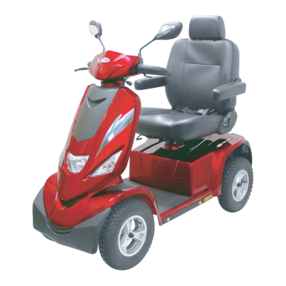
Service Manual
HS-928
This product has passed CE certifications, including GMP Taiwan,
ISO9001, and ISO13485.
※In case of any discrepancy between the illustrations and accessories in this manual
and the actual Scooter, the actual Scooter shall prevail.
※The Company reserves the right to design and modify this scooter.
S81201-92800
Advertisement

Related Manuals for C.T.M. HS-928


Summary of Contents for C.T.M. HS-928
- Page 1 Service Manual HS-928 This product has passed CE certifications, including GMP Taiwan, ISO9001, and ISO13485. ※In case of any discrepancy between the illustrations and accessories in this manual and the actual Scooter, the actual Scooter shall prevail. ※The Company reserves the right to design and modify this scooter.
- Page 2 Table of Contents : 1-1 Repair instructions ................01 2-1 Front shroud parts ................04 2-2 Front frame parts ................05 2-3 Rear shroud parts .................06 2-4 Rear frame parts ................07 2-5 Seat parts ..................08 2-6 Front wheel parts ................09 2-7 Rear wheel parts ................10 2-8 Brake set parts ................09...
- Page 3 1-1 Repair instructions Foreword : ※The repair manual is the technical data for maintenance and inspection of all parts of the HS-928. Its contents are arranged together with pictures and texts, with the key items of "work order", “work points”, and "inspection and adjustment" in order to provide maintenance standards for technical personnel.
- Page 4 1-1 Repair instructions Maintenance instructions : In order to keep your electric scooter in optimal use, please perform regular maintenance. Clean and check the following : ※Whether the front/rear tire pressure is within the normal range of 35-40 psi. ※Whether the front/rear tire pattern is lower than the normal value by more than 0.5 mm. ※Whether the frame and components are cleaned.
- Page 5 Parts Categories 2-01 Front shroud parts 2-02 Front frame parts 2-03 Rear shroud parts 2-04 Rear frame parts 2-05 Seat parts 2-06 Front wheel parts 2-07 Rear wheel parts 2-08 Brake set parts 2-09 Front slanting parts 2-10 Steering parts 2-11 Optional parts...
- Page 6 NO ITEM NUMBER DESCRIPTION 1 C-332110-92800-RD2 FRONT SHROUD ASSEMBLY 1 C-332100-92810-RD2 FRONT SHROUD ASSEMBLY 2 C-335110-92800 COVER , BUMPER FRONT 2 C-335110-92821 COVER , BUMPER FRONT 3 C-313300-92820 BATTERY 12V/100Ah 3 C-313300-92830 BATTERY 12V/100Ah 3a C-313300-92800 BATTERY ASSEMBLY 12V/100Ah 3a C-313300-92810 BATTERY ASSEMBLY 12V/100Ah 3a C-313275-92800 BATTERY 12V/75Ah...
- Page 7 NO ITEM NUMBER DESCRIPTION 1 531100-92822 FRAME COMP. , FRONT 1 531100-92833 FRAME COMP. , FRONT 2 C-317100-92800 CONTROLLER 160A 3 336110-92800 BAR ASSEMBLY 4 C-336215-56000 BALLS SET. 5 526680-52800 PADLOCK 6 C-331160-91500 HOLDER , SEAT LOWER BRACKET 7 C-315618-92801 Battery,Thermal Circuit Breaker 7a C-315300-92800 WIRE HARNESS BATTERY OUTPUT...
- Page 8 NO ITEM NUMBER DESCRIPTION C-342100-92800-RD2 SHROUD REAR COMP. C-342100-92820-RD2 SHROUD REAR COMP. C-345100-92800 COVER , BUMPER REAR ASSEMBLY C-345100-92810 COVER , BUMPER REAR ASSEMBLY C-345100-92820 COVER , BUMPER REAR ASSEMBLY C-345100-92831 COVER , BUMPER REAR ASSEMBLY C-342150-92801 FENDER RIGHT C-342160-92801 FENDER LEFT...
- Page 9 NO ITEM NUMBER DESCRIPTION 1 C-341310-92800 BRACKET , SUSPENSION 2 C-341210-92800 CUSHION COMP , REAR 2 C-341210-92810 CUSHION COMP , REAR...
- Page 10 NO ITEM NUMBER DESCRIPTION 1 571400-92801 SEAT COMP 2 372100-83801 SEAT BRACKET ASSEMBLY 3 C-372200-68600 SLIDE ASSEMBLY 4 C-372410-92801 HOLDER,GUIDE...
- Page 11 NO ITEM NUMBER DESCRIPTION 1 C-361200-92812 FRONT WHEEL ASSEMBLY 1 C-361200-92820 FRONT WHEEL ASSEMBLY 1 C-361200-92830 FRONT WHEEL ASSEMBLY 2 C-333310-92800 SUSEPNSION ASSEMBLY, FRONT WHEEL R 3 C-333410-92800 SUSEPNSION ASSEMBLY, FRONT WHEEL L 4 C-334110-92800 AXLE COMP., FRONT WHEEL R 5 C-334120-92800 AXLE COMP., FRONT WHEEL L 6 C-333210-92800...
- Page 12 NO ITEM NUMBER DESCRIPTION 1 C-351000-92800 DIFFERENTIAL COMP. 1 C-351000-91500 DIFFERENTIAL COMP. 2 C-311100-91511 MOTOR ASSEMBLY 15km 2 C-311100-91531 MOTOR ASSEMBLY 15km 2 C-311100-91521 MOTOR ASSEMBLY 12.8km 2 C-311100-91541 MOTOR ASSEMBLY 12.8km 2 C-311100-92881 MOTOR ASSEMBLY 18km (928) 2 C-311100-91550 MOTOR ASSEMBLY 15km (1100W) 3 C-362000-92812 REAR WHEEL ASSEMBLY...
- Page 13 NO ITEM NUMBER DESCRIPTION 1 565310-92800 CABLE 2 C-365110-92801 PANEL,REAR BRAKE CAM R 3 C-365210-92801 PANEL,REAR BRAKE CAM L...
- Page 14 NO ITEM NUMBER DESCRIPTION 1 C-324310-92801-RD2 FRONT SLANTING LID COMP. 1 C-324310-92812-RD2 FRONT SLANTING LID COMP. 1 C-324310-92821-RD2 FRONT SLANTING LID COMP. 1 C-324310-92841-RD2 FRONT SLANTING LID COMP. 2 C-324320-92820 BOX ASSEMBLY , KEY TYPE:A01 2 C-324320-92830 BOX ASSEMBLY , RANDOM KEY TYPE 2 C-324320-92840 BOX ASSEMBLY , KEY TYPE:A01 2 C-324320-92850...
- Page 15 7 C-318300-92800 LAMP ASS’Y,FRONT TURN SIGNAL-R 7 C-318320-92800 LAMP ASS’Y,FRONT TURN SIGNAL-R 8 C-318400-92800 LAMP ASS’Y,FRONT TURN SIGNAL-L 8 C-318420-92800 LAMP ASS’Y,FRONT TURN SIGNAL-L 9 525210-61500 COVER , STEERING JOINT 10 C-324335-92800 GUARD+VEL-CRO...
- Page 16 NO ITEM NUMBER DESCRIPTION 1 521100-92801 STEERING COMP. 2 C-321220-92800 GRIP , HANDLE BAR 3 C-316300-57001 STARTER ASSEMBLY 4 C-326120-68600 LEVER , BRAKE RIGHT 5 C-325300-89003 STEERING ADJ ASSEMBLY 6 C-325390-92810 REGULATOR ROD 7 C-325120-89001 JOINT B,STEERING ADJ LOWER 8 326200-92800 BACK MIRROR COMP 9 C-314280-89001 CHARGER COMP.
- Page 17 NO ITEM NUMBER DESCRIPTION 1 377200-92800 CANE HOLDER COMP 2 377300-28000 OXYGEN CYLINDER COMP 3 377100-28001 BRACKET COMP., CANE 4 377600-28000 BRACKET ASSEMBLY , WALKER 5 377400-28000 REAR BASKET COMP. 6 379830-92800 GOLF HOLDER ASSEMBLY 7 C-331160-72800 LIFTING GEAR ASSEMBLY 8 7-ABL0 SHROUD TOUCH UP PAINT BL0 8 7-ABU1...
- Page 18 8 7-ASG1 SHROUD TOUCH UP PAINT SG1 8 7-ASG5 SHROUD TOUCH UP PAINT SG5 8 7-AWH1 SHROUD TOUCH UP PAINT WH1...
- Page 19 Maintenance Manual : 3-1 Powering off the battery 3-2 Battery removal 3-3 Battery connection cable set maintenance 3-4 Battery connection cable set disassembly 3-5 Charging operation instructions 4-1 Main switch and upper control panel instructions 4-2 Upper control panel adjustment 4-3 Control panel maintenance 4-4 Panel wiring instructions 4-5 Maintenance of the VR initiator controller...
- Page 20 3-1 Powering off the battery : ※No tools required 1.Ensure the scooter’s power is off. 2.Adjust the gearshift of the scooter to “D.” 3.Pull the handle on the left side of the seat. 4.Remove the scooter seat. 5.Remove the upper cover of 6.Remove the scooter power ※Power cut-off is completed.
- Page 21 ※The red connector of the power cable shall be connected to the red positive terminal; the black connector shall be connected to the black negative terminal. ※To replace the battery, please remove the screws of each positive and negative terminal in order.
- Page 22 ※In order to avoid overvoltage of the battery, the battery connection cable set has a high voltage protection function. If the battery connection cable set is damaged, please replace with a new one immediately. ※When reassembling the battery connection cable, please pay attention to the battery "+"...
- Page 23 •Battery electricity table : Battery residual display Electric 100% 20% or (1 cell quantity 6 cells 5 cells 4 cells 3 cells 2 cells less flashes) Cell Warning number indicator, status continuous display flashing After the power is turned on, an alarm will be set off when the electric quantity is lower than 30% (three beeps) •Charging indicating table : Electric quantity...
-
Page 24: Speed Display
4-1 Main switch and upper control panel instructions : ※No tools required Main power switch (A) 1.Rotate clockwise to “ turn power on ”. 2.Rotate counterclockwise to " turn power off ". ※The main switch shall be turned on when driving the scooter. Please turn off the main switch when the scooter is stopped so as not to waste electricity. - Page 25 4-2 Upper control panel adjustments : ※No tools required Panel function setting steps Press K to switch to the mode to be set 1.Time mode 2.Temperature mode 3.Speedometer mode 4.Mileage accumulation mode 5.Trip accumulation mode TRIP ※Pressing L+M at the same time for at least 3 seconds will enter the setting state.
- Page 26 4-3 Control panel maintenance : ※Cross tool x 1pcs ※Straight tool x 1pcs 1.Refer to 3-1 Powering off the battery to power off the scooter. 2.Remove the two lock points on the top cover. 3.Use the straight tool to open the control panel. ※If you have problems with the control panel, please reconnect the main cable connector first.
- Page 27 4-5 Maintenance of the VR initiator controller : ※Cross tool x 1pcs 1.Refer to 3-1 Powering off the battery to power off the scooter. 2.Remove the head actuating lever clamping screws (M4 x 12L x 2pcs). 3.Please refer to 4-3 Upper control panel maintenance to open the control panel. 4.Remove the head actuating lever clamping screws (M4 x 12L x 2pcs).
- Page 28 5-1 Front slanting maintenance : ※Cross tool x 1pcs 1.Refer to 3-1 Powering off the battery to power off the scooter. 2.Please refer to 4-6 Steering cover maintenance to remove the cover. 3.Remove the screws around the front box (M4 x 12L x 8pcs). 4.Remove the front slanting connector (3pcs).
- Page 29 5-3 Turning deceleration set maintenance : ※Cross tool x 1pcs 1.Refer to 3-1 Powering off the battery to power off the scooter. 2.Please refer to 5-1 Front slanting maintenance to remove the front slanting. 3.Remove the turning deceleration set connector. 4.Remove the locking screw (M4 x 13L x 2pcs).
- Page 30 5-4 Temperature sensor : ※Cross tool x 1pcs 1.Refer to 3-1 Powering off the battery to power off the scooter. 2.Please refer to 5-1 Front slanting maintenance to remove the front slanting. 3.Remove the temperature sensor connector. 4.The temperature sensor can now be removed from the slot. ※Please follow the above steps in reverse for reassembly and replacement.
- Page 31 5-6 Front turn light maintenance : ※Cross tool x 1pcs 1.Refer to 3-1 Powering off the battery to power off the scooter. 2.Please refer to 5-1 Front slanting maintenance to remove the front sloping cover. 3.Remove the front (left) turn light connector on the front box. 4.Remove the front (left) turn light screws (M4 x 12L x 3pcs) 5.Take out the front (left) turn light from the slot.
- Page 32 5-8 charging port maintenance : ※Cross tool x 1pcs 1.Refer to 3-1 Powering off the battery to power off the scooter. 2.Please refer to 5-1 Front slanting maintenance to remove the front sloping plate. 3.Remove the charging port connector. 4.Remove the charging port screws from the front box (4 pcs). 5.The entire set of the charging base now can be removed.
- Page 33 6-1 Steering frame maintenance : ※Hex wrench 8 x 2pcs ※internal hexagonal wrench 4 x 1pcs ※Hex wrench 6 x 1pcs 1.Refer to 3-1 Powering off the battery to power off the scooter. 2.Please refer to 4-6 Head steering cover maintenance to remove the cover. 3.Remove the screw set (M8 x 30Lx 1pcs) on the steering.
- Page 34 6-3 Front shroud upper cover maintenance : ※Cross tool x 1pcs ※Sleeve tool #10 x 1pcs 1.Refer to 3-1 Powering off the battery to power off the scooter. 2.Please refer to 3-2 Battery removal. 5-1 Front slanting maintenance. 6-1 Steering frame maintenance. 6-2 Maintenance of front cover of front box.
- Page 35 6-5 Center bar maintenance : ※Hex wrench 10 x 1pcs ※Hex wrench 8 x 2pcs ※Hex wrench 13 x 1pcs 1.Refer to 3-1 Powering off the battery to power off the scooter. 2.Please refer to 6-1 Steering frame repair to remove the Steering. 6-3 Front shroud upper cover maintenance to remove the front shroud upper cover.
- Page 36 7-1 Seat board maintenance : ※Hex wrench 13 x 2pcs 1.Refer to 3-1 Powering off the battery to power off the scooter. 2.Please remove the seat first. 3.Remove the seat board locking nut (M8 x 4pcs). 4.Remove the seat rail screws (M8 x15L x 4pcs). 5.The entire seat can now be removed.
- Page 37 7-3 Seat bracket maintenance : ※Hex wrench 17 x 2pcs ※Cross tool x 1pcs 150+-15kgf-cm 1.Refer to 3-1 Powering off the battery to power off the scooter. 2.Remove the upper set of fixing screws (M8 x35L x 1pcs). 3.Remove the upper set of fixing screws (M10 x20L x 4pcs). 4.The entire set of the seat holder can now be removed.
- Page 38 8-1 Front wheel maintenance : ※Socket wrench #17 x 1pcs ※internal hexagonal wrench #8 x 1pcs 1.Refer to 3-1 Powering off the battery to power off the scooter. 2.Please keep the front wheel of the scooter suspending in midair. 3.Remove the nut cover of the rim outside 4.Remove the lock nut (M10) and the spacer.
- Page 39 ※When reassembling the meter gear, please note the direction of the slot before fixing. ※If the upper-control shows an abnormal rotating speed, please first check whether the connectors on both ends of the meter gear wire are fixed. Refer to 1. Upper-control plate maintenance.
- Page 40 8-4 Left/right brake adjustment : ※Hex wrench #10 x 1pcs 1.Refer to 3-1 Powering off the battery to power off the scooter. 2.Refer to 8-3 Rear wheel maintenance to remove the rear wheel. 3.Loosen the right brake plate adjustment screw. ※It is the same for the left/right brake cables.
- Page 41 8-7 Rear cover maintenance : ※Cross tool x 1pcs 1.Refer to 3-1 Powering off the battery to power off the scooter. 2.Remove the scooter seat and the rear shroud upper cover. 3.Remove the tail light connector (left : black / right : red). 4.Remove the upper locking screw (M4 x12L x 2pcs).
- Page 42 9-1 Motor maintenance : ※#5 Allen wrench x 1pcs 1.Refer to 3-1 Powering off the battery to power off the scooter. 2.Refer to 7-3 Controller maintenance to unplug the motor power line. 3.Remove the motor fixing screws (M6 x 50L x 4pcs). 4.The motor can now be removed.
- Page 43 9-3 Differential mechanism maintenance : ※Hex wrench 13 x 2pcs 1.Refer to 3-1 Powering off the battery to power off the scooter. 2.Refer to 3-3 Controller maintenance to unplug the motor power line. 3.Remove the motor mount screws (M8 x 45L x 4pcs) on both sides. 4.The motor holder on both sides can now be removed.
- Page 44 9-5 Front shock absorber maintenance : ※Hex wrench 17 x 2pcs 1.Refer to 3-1 Powering off the battery to power off the scooter. 2.Refer to 6-3 Front shroud upper cover maintenance to remove the upper cover. 3.Remove the rear shock absorber upper fixing screw set (M10 x 67L x 1pcs). 4.Remove the rear shock absorber lower fixing screw set (M10 x 45L x 1pcs).
- Page 45 6.Cut the main trace strap on the left side of the front frame (2pcs). 7.The main line passes through the groove at the bottom of the frame. Please pull it directly away from the groove. 8.The main line extends to the top of the rear frame and cuts the strap (x 1pcs). ※The entire brake cable can now be removed.
- Page 46 9-7 Brake cable maintenance : ※Scissors x 1pcs ※Hex wrench #10 x 1pcs 1.Refer to 3-1 Powering off the battery to power off the scooter. 2.Refer to 3-2 Battery removal to remove the battery connector. 4-4 Panel wiring instruction to remove the panel wiring. 4-6 Steering cover maintenance to remove the cover.
- Page 47 Check for troubleshooting Checked part Check content Processing method N-D lever Is the gear adjustment abnormal? 9-2 Electromagnetic brake maintenance Buzzer Does it set off a sound when working? 4-3 Control panel maintenance Is the battery indicator light on? Battery indicator 3-5 Charging operation instruction Is the low power alarm displayed? Please clean and wipe...
Need help?
Do you have a question about the HS-928 and is the answer not in the manual?
Questions and answers