
Related Manuals for CAME BPT DC/08


Summary of Contents for CAME BPT DC/08
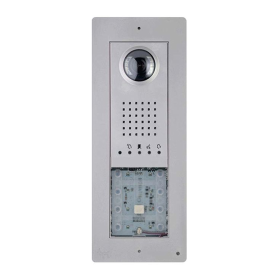
- Page 1 Video FB00864-EN entry panel DC/08 - DVC/08 DC/08ME - DVC/08ME PROGRAMMING MANUAL EN English...
-
Page 2: General Warnings
General warnings Important personal safety instructions: READ CAREFULLY! Installation, programming, commissioning and maintenance must only be performed by qualified and experienced • personnel in compliance with applicable regulations. Wear antistatic shoes and clothing if working on the control board. • Keep hold of these warnings. -
Page 3: Technical Data
Red - Call in progress Green - Door open Yellow - Conversation in progress Blue - System busy Technical data Type DC/08-DVC/08 - DC/08 ME-DVC/08 ME Power supply (VDC) 14-18 Absorption (mA) Consumption in stand-by mode (mA) Storage temperature (°C) -25 ÷... -
Page 4: Connection Examples
Connection examples VA/08 +D – +V1– +V2– +D – +V3– +V4– MINI USB VLS/101 DATI PROG +12V DVC/08 DVC/08ME VA/08 +D – +V1– +V2– +D – +V3– +V4– MINI USB VLS/101 DATI PROG DC/08 DC/08ME... - Page 5 Connection examples VA/08 +D – +V1– +V2– +D – +V3– +V4– MINI USB DATI PROG AC/200 +12V VTX/100 DC/08 VIDEO OUT DC/08ME VA/08 +D – +V1– +V2– +D – +V3– +V4– MINI USB DATI PROG AC/200 VTX/100 DC/08 DC/08ME 75 ohm...
-
Page 6: Manual Programming Of Entry Panels
Manual programming of entry panels It is possible to program only one or multiple audio/video entry panels with the same calls (unless the use of “blind modules” inhibits one or more). The entry panels (connected to the same power supplier) can be programmed with different types of keys, following the sequence shown to the side. -
Page 7: Initial Programming With One Entry Panel
Initial programming with ONE entry panel Accessing programming. Press the PROG key on the power supplier 1 until the >3’’ PROG PROG LED turns on. If the PROG LED turns off suddenly, this indicates a malfunction in the connection between the power supplier and the entry panel. Check the connections and return to programming. -
Page 8: Initial Programming With Multiple Entry Panels
External entry panel illumination level adjustment. During the call button programming of any internal receiver the external entry panel illumination level can be adjusted up or down (with the handset lifted if present). DATI Pressing the “self-connection ” button on the internal receiver causes the external entry panel camera for which the illumination level is to be adjusted to be activated. -
Page 9: Reprogramming Procedure
External entry panel illumination level adjustment. During call button programming the external entry panel illumination level can be adjusted up or down as previously described. Reprogramming procedure Accessing programming. Press the PROG key on the power supplier 1 until the PROG PROG LED turns on. -
Page 10: Programming With Dna
External entry panel illumination level adjustment. During call button programming PROG the external entry panel illumination level can be adjusted up or down as previously described. In the case that the call buttons are ONLY located on the ADDITIONAL PUSH BUTTON PANELS, proceed as indicated in NOTE on page 7. -
Page 11: Code And Tag Entry
Code and tag entry RFID Place the power supplier RFID PROG jumper in position “+” 1: the power supplier PROG PROG PROG LED will flash slowly as will also the signalling LEDs with the configuration in fig. 2. If the LEDs turn off suddenly, this indicates a malfunction in the connection Ð... - Page 12 Badges and Codes. Entry panel with buttons: press the call key for at least 10 beep seconds F relative to the GROUP for which you want to cancel the codes and, after >10’’ the beep, press the key (briefly) a second time G. This will delete ALL codes and badges of any type of the GROUP.
Need help?
Do you have a question about the DC/08 and is the answer not in the manual?
Questions and answers