
Related Manuals for CAME BPT AGT V200


Summary of Contents for CAME BPT AGT V200
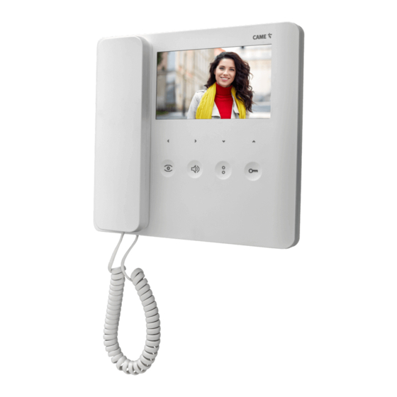
- Page 1 AGT KIT V200 + TARGHA FA01427-EN AGT V200 TARGHA 200 VA/200 INSTALLATION MANUAL AGTK200V03 English...
-
Page 2: General Precautions
CONTENTS OF THE KIT AGT A200 VA/200 TARGHA 200 General precautions Read the instructions carefully before beginning the installation and carry out the procedures as specifi ed by the manufacturer. • The product must be installed, programmed, commissioned and serviced by qualifi ed technicians, correctly trained with regard to •... -
Page 3: Technical Data
AGT V200 Description of AGT V200 Internal video receiver. Function of terminals and jumper Terminal board M1 Video signal Coaxial cable Video signal screen If the line does not continue, connect a 75Ω resistor (violet- green-black-gold) between terminals 3 and 4. -
Page 4: Installation
① ② Installation Detach the video receiver from the metal support by pressing the plastic button and sliding the device smoothly off the support • Fix the wall support to the round Ø 60 mm recessed box , to the rectangular box 503 , or to the Ophera (PHI) recessed box •... - Page 5 VA/200 Installation The power supplier must ALWAYS be installed horizontally. The device can be installed on a DIN rail (EN 50022) in an ap- propriate electric panel or it may be wall-mounted using the pro- tective terminal covers. 43,5 For disassembly, proceed as shown in fi gure For the overall dimensions see fi...
- Page 6 Features Terminal boards D Coaxial cable connection Terminal boards A 3 Video signal Mains 4 Video signal shield 7 Call no. 1 Terminal boards B Coaxial cable connection – Power supply 17,5 VDC (*) 3 Video signal to entry panel 4 Video signal shield 7 Call no.
- Page 7 OPERATING CHARACTERISTICS System activation timer The installation remains active for 30 s following a call at the entry panel. If the handset is lifted during this interval, the activation time is increased by 30 s and may be extended to a maximum of 90 s. by adjusting potentiometer TV, fi gure , pag.
- Page 8 TARGHA 200 COMPONENTS Audio-video module HAVC/200 Surface housing Hole plugs Embedding box Cable guide joint Joint Chassis Screws and anchors Cable guide joints Button Spacer Micro-contact Screws Button spring Plate Micro-contact Lighting module Cable-clamp plate...
- Page 9 ADDITIONAL PUSH-BUTTON PANEL Plate Micro-contacts with common call Lighting module Cable-clamp plates Hole plug...
-
Page 10: Recessed Installation
Recessed installation The embedding box HTS must be fi tted fl ush with the wall at an appropriate height. In the case of video entry panels, the height should be such as to exploit the features of the camera to the full. Fit the spacer into embedding boxes to avoid deformation Insert the audio-video module at the top, near to the top mould- ing of the chassis... -
Page 11: Wall Mounting
Wall mounting Apply the two hole plugs at the base Fit the embedding box HBP (3-module or round Ø 65mm version) fl ush with the wall at an appropriate height. In the case of video entry panels, the height should be such as to exploit the features of the camera to the full. -
Page 12: Side-By-Side Recessed Installation
Closure of the cover plate In order to fi t the front plate, fi rst insert the upper part in the top moulding and then, using a Allenkey s 2.5, tighten the lock screw Side-by-side recessed installation For horizontal or vertical combinations, remove the hole plugs and insert the cable guide joints. -
Page 13: Side-By-Side Wall Installation
Side-by-side wall installation For horizontal combinations, insert the two hole plugs on the outside, at the bottom inside the cable guide joint and top inside the joint Fasten the bases to the wall using the screws and screw anchors supplied Terminal function Terminal boards HAV/200... -
Page 14: Orientation Of The Camera
Orientation of the camera CCD colour camera which can be rotated manually both hori- zontally and vertically by ± 11° , with fi xed-focus lens (see for the dimensions of the fi eld of view) and phonic group (the microphone can be removed and fi tted in a remote position where the installation features so require). - Page 15 The product complies with the relevant directives in force. Dismantling and disposal. Dispose of the packaging and the device responsibly at the end of its life cycle, in compliance with the laws in force in the country where the product is used. The recyclable components are marked with a symbol and the material ID marker.
- Page 16 CAME S.p.A. Via Martiri Della Libertà, 15 31030 Dosson di Casier - Treviso - Italy tel. (+39) 0422 4940 - fax. (+39) 0422 4941...
Need help?
Do you have a question about the AGT V200 and is the answer not in the manual?
Questions and answers