Wilo DrainLift SANI-M Installation And Operating Instructions Manual
Hide thumbs
Also See for DrainLift SANI-M:

Related Manuals for Wilo DrainLift SANI-M


Summary of Contents for Wilo DrainLift SANI-M
- Page 1 Pioneering for You Wilo-DrainLift SANI-M en Installation and operating instructions · 2552853 • Ed.03/2023-06...
- Page 2 DrainLift SANI-M https://qr.wilo.com/481...
-
Page 3: Table Of Contents
Staff qualifications.............. 14 Installation types.............. 14 Operator responsibilities............ 14 Installation ................ 14 Electrical connection ............ 20 7 Commissioning ................. 22 Staff qualifications.............. 22 Operator responsibilities............ 22 Operation ................ 22 Test run ................ 22 Follow-up time.............. 23 Setting the venting screw.......... 23 8 Operation .................. 23 Installation and operating instructions • Wilo-DrainLift SANI-M • Ed.03/2023-06... -
Page 4: Subject To Change
All rights reserved. Subject to change Wilo reserves the right to change the listed data without prior notice and is not liable for technical inaccuracies and/or omissions. The illustrations vary from the original and are in- tended as a sample representation of the device. - Page 5 Danger due to bacterial infection Warning – risk due to hot surfaces Wear protective helmet. Wear safety shoes. Wear safety gloves. Wear respiratory mask. Wear safety glasses. Be aware about the instructions. Useful information Installation and operating instructions • Wilo-DrainLift SANI-M • Ed.03/2023-06...
-
Page 6: Electrical Work
The mentioned branded articles are non-binding suggestions. Similar products from other brands can also be used. The pre- requisite is the fulfilment of the mentioned standards. WILO SE accepts no liability for the mentioned articles regarding their conformity to the relevant standards. Electrical work •... -
Page 7: Monitoring Devices
Only use undamaged tanks (no cracks, leaks, porous material). Switch off lifting units with damaged tanks immediately. • Ensure that all connections for the inlet, discharge pipe, and ventilation are sealed tightly and executed according to the local regulations. Installation and operating instructions • Wilo-DrainLift SANI-M • Ed.03/2023-06... -
Page 8: Transport
Open all shut-off valves in the inlet and discharge pipe. • The maximum inflow must be lower than the maximum output of the system. • Do not open the inspection opening. • Ensure the operating space is well ventilated. Installation and operating instructions • Wilo-DrainLift SANI-M • Ed.03/2023-06... -
Page 9: 2.11 Cleaning And Disinfection
• For backflow resistant drainage in cases where the discharge point is below the back- flow level NOTICE! Install grease traps upstream of the lifting unit if pumping greasy sewage! Installation and operating instructions • Wilo-DrainLift SANI-M • Ed.03/2023-06... -
Page 10: Improper Use
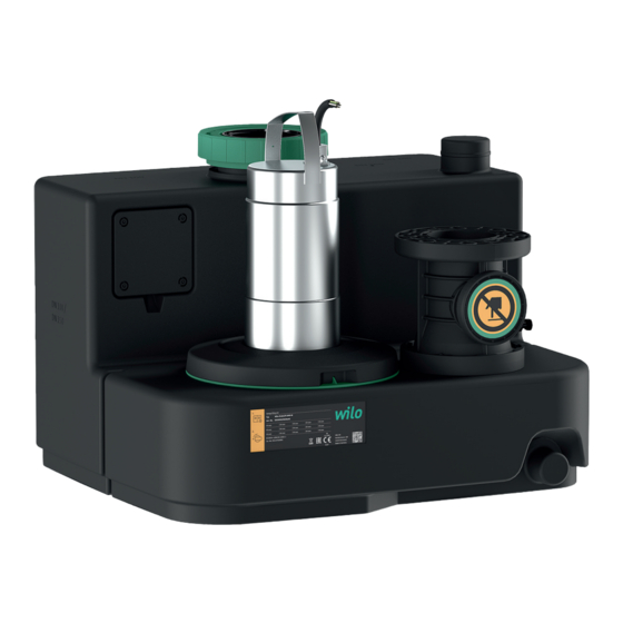
Surface-cooled (air) or self-cooling (sheath flow cooling) motor with thermal motor monit- Fig. 1: Overview oring. Pre-installed switchgears for automatic operation: Wilo-Control MS-L • Collective fault signal with potential-free contact • Integrated and mains-independent alarm Installation and operating instructions • Wilo-DrainLift SANI-M • Ed.03/2023-06... -
Page 11: Materials
4 = operating mode: S1, switchgear: Control EC-L Version for aggressive fluids Technical data Approved field of application Max. pressure in the discharge pipe 6 bar (87 psi) Max. delivery head See rating plate Installation and operating instructions • Wilo-DrainLift SANI-M • Ed.03/2023-06... -
Page 12: Manufacturer Date
Lifting unit with switchgear and connection cable with plug Scope of delivery • Flange connector DN 80 (90 mm)/DN 100 (110 mm) • Collar DN 100 (110 mm) for discharge connection Installation and operating instructions • Wilo-DrainLift SANI-M • Ed.03/2023-06... -
Page 13: Accessories
Permitted storage temperature: -15 ... 60 °C (5 ... 140 °F), max. humidity: 90 %, non- condensing. We recommend frost-proof storage. Storage temperature: 5 ... 25 °C (41 ... 77 °F), relat- ive humidity: 40 ... 50 %. • Drain the collection tank completely. Installation and operating instructions • Wilo-DrainLift SANI-M • Ed.03/2023-06... -
Page 14: Installation And Electrical Connection
Ensure a free space of min. 60 cm (2 ft) around the unit. • In the event of an accident: Provide pump sump in the operating space, min. dimensions: 500x500x500 mm (20x20x20 in). Select pump accordingly. Ensure that manual drainage is feasible. Installation and operating instructions • Wilo-DrainLift SANI-M • Ed.03/2023-06... - Page 15 No tensile or compressive forces must act on the lifting unit. • Pressure resistance of pipework and pipe connections • Tensile strength of the pipe connections (= longitudinal force fit connection) • Connect the pipes free of stress and vibrations. Installation and operating instructions • Wilo-DrainLift SANI-M • Ed.03/2023-06...
- Page 16 Fasten the switchgear to the wall to protect the switchgear from flooding (see switchgear instructions). 10. Lay the connection cable according to regulations. ▶ Lifting unit installed to protect it against buoyancy and twisting. Next step: Connect the discharge pipe. Installation and operating instructions • Wilo-DrainLift SANI-M • Ed.03/2023-06...
- Page 17 Discharge pipe connected. Next step: Connect the inlet. 6.4.7 Connecting the inlet The inlet can be located in the areas indicated on the rear wall, both side walls and the tank roof, as desired. Installation and operating instructions • Wilo-DrainLift SANI-M • Ed.03/2023-06...
- Page 18 Lifting unit installed properly. ✓ Inlet pipe installed to the collection tank according to the consulting documents. ✓ Installation material prepared: 1x hole saw 124 mm (5 in) included in the scope of delivery 1x drill Installation and operating instructions • Wilo-DrainLift SANI-M • Ed.03/2023-06...
- Page 19 The collection tank is pumped out via the drain connection for inspection work or in the event of an accident. Do not connect inlets to the drain connection! Otherwise, the collection tank cannot be drained in case of emergency! Installation and operating instructions • Wilo-DrainLift SANI-M • Ed.03/2023-06...
-
Page 20: Electrical Connection
– DrainLift SANI-M…M/…: CEE 7/7 (Schuko) Three-phase current: – DrainLift SANI-M…T/…: CEE 16A, 3P+N+PE, 6 h, clockwise rotating field 6.5.3 Switchgear The switchgear is pre-wired and factory-set. Lay all connection cables to the switchgear and mains connection according to local regulations. CAUTION! Install the switchgear so... - Page 21 NOTICE! For the position of DIP switch 3, refer to the installation and operating instruc- tions of the switchgear! Wilo-Control EC-L switchgear The switching points are set via the menu for the Wilo-Control EC-L switchgear. Set the following values in the specified menus: Switching points Pump ON: 180 mm (7 in)
-
Page 22: Commissioning
Connections checked for correctness. Activate the lifting unit: Insert plug into socket. Select automatic mode on the switchgear. Open the shut-off valve in the discharge pipe. NOTICE! The shut-off valve in the inlet remains closed! Installation and operating instructions • Wilo-DrainLift SANI-M • Ed.03/2023-06... -
Page 23: Follow-Up Time
Risk of burns from hot surfaces! The motor can get hot during operation and present a risk of burning skin if touched • Allow the motor to cool down to ambient temperature after switching it off. Installation and operating instructions • Wilo-DrainLift SANI-M • Ed.03/2023-06... - Page 24 If the lifting unit completely fails, pump out the sewage using a diaphragm hand pump. Close the shut-off valve in the inlet. Close the shut-off valve in the discharge pipe. Pump sewage into the discharge pipe using the diaphragm hand pump. Installation and operating instructions • Wilo-DrainLift SANI-M • Ed.03/2023-06...
- Page 25 The lifting unit is now decommissioned. If the lifting unit is decommissioned for an extended period, perform a functional check at regular intervals (quarterly). CAUTION! Perform the functional check as described under “Test run”. Installation and operating instructions • Wilo-DrainLift SANI-M • Ed.03/2023-06...
- Page 26 DANGER! Health risk due to contact with sewage! The remaining sewage flows out of the collection tank via the drain connection. Collect sewage in suitable tanks and feed it into the sewer system. Installation and operating instructions • Wilo-DrainLift SANI-M • Ed.03/2023-06...
- Page 27 Dispose of worn protective clothing according to the local regulations. • Collect the operating fluid in suitable tanks. 12.2 Oils and lubricants • Immediately clean up leaked liquid. • Dispose of the operating fluid according to the local regulations. Installation and operating instructions • Wilo-DrainLift SANI-M • Ed.03/2023-06...
- Page 28 • Observe the locally applicable regulations. Consult your local municipality, the nearest waste disposal site, or your retailer for informa- tion on proper disposal. See www.wilo‑recycling.com for more information about recycling. Installation and operating instructions • Wilo-DrainLift SANI-M • Ed.03/2023-06...
- Page 32 Local contact at www.wilo.com/contact WILO SE Wilopark 1 44263 Dortmund Germany T +49 (0)231 4102-0 T +49 (0)231 4102-7363 wilo@wilo.com Pioneering for You www.wilo.com...
Need help?
Do you have a question about the DrainLift SANI-M and is the answer not in the manual?
Questions and answers