
Related Manuals for Wilo Economy CO-1 Series


Summary of Contents for Wilo Economy CO-1 Series
- Page 1 Pioneering for You Wilo-Economy CO-1... Wilo-Economy CO/T-1... en Installation and operating instructions · 2554893 • Ed.01/2023-11...
- Page 2 Economy CO-1...-EC https://qr.wilo.com/637 Economy CO/T-1...-EC https://qr.wilo.com/606...
-
Page 19: Table Of Contents
11 Spare parts ................ 46 12 Disposal.................. 47 12.1 Oils and lubricants .............. 47 12.2 Water-glycol mixture............ 47 12.3 Protective clothing ............. 47 12.4 Information on the collection of used electrical and elec- tronic products.............. 47 Installation and operating instructions • Wilo-Economy CO-1..., Wilo-Economy CO/T-1... • Ed.01/2023-11... -
Page 20: General
All rights reserved. Subject to change Wilo shall reserve the right to change the listed data without notice and shall not be liable for technical inaccuracies and/or omissions. The illustrations used may differ from the ori- ginal and are intended as an exemplary representation of the product. - Page 21 General danger symbol Danger caused by electric voltage General warning symbol Warning – suspended loads Personal protective equipment: wear a safety helmet Personal protective equipment: wear hearing protec- tion Installation and operating instructions • Wilo-Economy CO-1..., Wilo-Economy CO/T-1... • Ed.01/2023-11...
-
Page 22: Personnel Qualifications
Circuit breaker • Design the power and switching characteristics of the circuit breakers according to the rated current of the connected product. Installation and operating instructions • Wilo-Economy CO-1..., Wilo-Economy CO/T-1... • Ed.01/2023-11... -
Page 23: Transport
• All rotating parts must stop. • Clean the device thoroughly. During operation • Wear protective equipment according to work regulations. • Demarcate and cordon off the working area. Installation and operating instructions • Wilo-Economy CO-1..., Wilo-Economy CO/T-1... • Ed.01/2023-11... -
Page 24: Maintenance Tasks
Use is not permitted for persons under the age of 16. • Persons under the age of 18 must be supervised by a techni- cian! • Use is not permitted for persons with limited physical, sensory or mental capacities! Installation and operating instructions • Wilo-Economy CO-1..., Wilo-Economy CO/T-1... • Ed.01/2023-11... -
Page 25: Application/Use
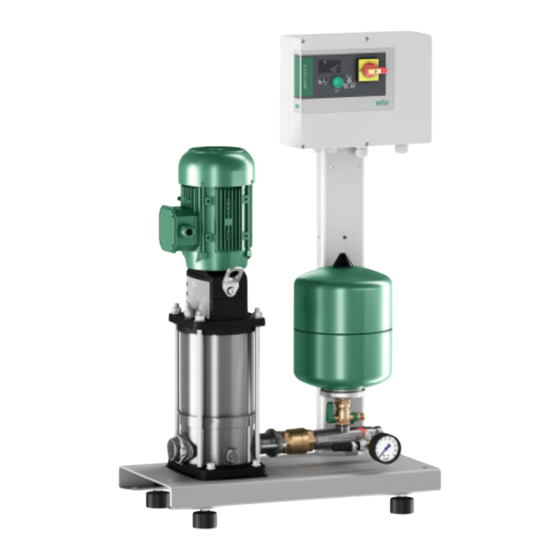
The CO-1.. pressure-boosting system type (Fig. 1a, Fig. 1b) can be connected directly or indirectly to the public water network using a break tank from the Wilo range or a break tank to be provided by the customer. The CO/T... pressure-boosting system type (Fig. 1c) is supplied with an integrated break tank and is therefore already prepared for indirect connection to the public water supply network. -
Page 26: Product Description
Including WMS kit (low-water cut-out switchgear for opera- tion with supply pressure) Technical data see catalogue/data sheet Max. volume flow Max. delivery head see catalogue/data sheet Speed 2800 – 2900 rpm (constant speed) Installation and operating instructions • Wilo-Economy CO-1..., Wilo-Economy CO/T-1... • Ed.01/2023-11... - Page 27 (see rating plate) Max. permissible inlet Indirect connection (but max. 6 bar) pressure Diaphragm expansion 8 l tank Scope of delivery The pressure-boosting system is supplied ready for connection. Installation and operating instructions • Wilo-Economy CO-1..., Wilo-Economy CO/T-1... • Ed.01/2023-11...
-
Page 28: Scope Of Delivery
Installation and operating instructions for the signal transmitter, if applicable • Spare parts list, if applicable Accessories Accessories must be ordered separately as required. The accessories from the Wilo range include the following: • Open break tank (Fig. 9a, 9b) •... - Page 29 Consisting of: • Diaphragm expansion tank (Item 9) with lockable throughflow fitting (Item 10) and drain valve Pressure sensor kit (Fig. 2) Consisting of: • Pressure gauge (Item 11) • Pressure sensor (Item 12-a) Installation and operating instructions • Wilo-Economy CO-1..., Wilo-Economy CO/T-1... • Ed.01/2023-11...
-
Page 30: Function
(Item 1) with three-phase current motor (Item 17). The pump is supplied with water via the inlet connection (Item 4). For suction mode (CO-1) from lower-lying tanks, a separate, vacuum- Installation and operating instructions • Wilo-Economy CO-1..., Wilo-Economy CO/T-1... • Ed.01/2023-11... -
Page 31: Transport And Storage
In the case of an indirect connection (system separation by non-pressurised break tank), provide a level-dependent signal transmitter installed in the break tank as a dry-running protection device. When using a Wilo break tank, a float switch (Fig. 9b – Item 52) is already included in the scope of delivery. -
Page 32: Delivery
Fixation lugs on base frame: Sling chain with sling hook with safety latch. – Screw in the loosely supplied ring eyelets: Sling chain or polyester webbing sling with shackle. Installation and operating instructions • Wilo-Economy CO-1..., Wilo-Economy CO/T-1... • Ed.01/2023-11... -
Page 33: Storage
The system should be freely accessible from at least two sides. • Wilo advises against installation and operation near living rooms and bedrooms. • To avoid the transmission of structure-borne noise and to ensure a stress-free connec- tion to upstream and downstream pipes, compensators (Fig. 7 –... - Page 34 DIN 1988) and was checked at the factory to make sure it functions correctly. When used in drinking water applications, the complete drinking water installation has to be handed over to the operator in a perfect state of hygiene. The following applies here: Installation and operating instructions • Wilo-Economy CO-1..., Wilo-Economy CO/T-1... • Ed.01/2023-11...
- Page 35 In the event of indirect connection: • If a Wilo break tank is used, a float switch for level monitoring is provided as standard as a means of protection against low water level. Establish the electrical connection to the control device of the system in accordance with the installation and operating instruc- tions and circuit diagram for the control device.
- Page 36 1.1 times the admissible level. Installation and operating instructions • Wilo-Economy CO-1..., Wilo-Economy CO/T-1... • Ed.01/2023-11...
- Page 37 CAUTION Risk of property damage due to incorrect handling. PE tanks from the Wilo range are only designed to collect clean water. • Clean and flush the break tank before filling it. • Comply with the maximum water temperature of 40 °C.
- Page 38 (see recommenda- tions of DIN 1988). The flexible connection pipes in the Wilo range consist of a high-quality stainless steel cor- rugated hose with stainless steel braiding. In the case of pipes with threaded connections, use for stress-free installation of the pressure-boosting system and in the event of slight pipe displacement (Fig. 7 –...
-
Page 39: Electrical Connection
External fuse protection of the connection cable for the pressure-boosting system must be provided in accordance with the applicable local regulations (e.g. VDE0100, part 430) in compliance with the details in the installation and operating instructions. Installation and operating instructions • Wilo-Economy CO-1..., Wilo-Economy CO/T-1... • Ed.01/2023-11... -
Page 40: Commissioning
Dry running can lead to the pump developing leakages and to motor overload. • Ensure that the pump does not run dry to protect the mechanical seal and the plain bearings. Installation and operating instructions • Wilo-Economy CO-1..., Wilo-Economy CO/T-1... • Ed.01/2023-11... -
Page 41: Preparations And Control Measures
NOTICE We recommend that the initial commissioning of the system is per- formed by the Wilo customer service department. • Contact your dealer, your nearest Wilo representative or the Wilo cus- tomer service department. NOTICE Automatic activation after power cut Depending on the process, the product is activated and deactivated us- ing separate controls. -
Page 42: Protection Against Low Water Level (Wms)
Observe the respective manufacturer’s documentation for the compo- nent. 7.2.2 Operation with separate break With Wilo break tanks, the level-dependent low-water monitoring is performed via a float tank (inlet mode) switch (see example Fig. 9a, 9b). • Connect the float switch before commissioning in the control device. -
Page 43: Maintenance
If necessary, correct the pressure by filling with nitrogen. (PN 2 = pump switch-on pres- sure p minus 0.2 – 0.5 bar or value given in the table on the tank (Fig. 4) – Wilo cus- tomer service). If the pressure is too high, release nitrogen from the valve. - Page 44 Check the inlet pipe and, if necessary, remove the clogging or open the shut-off valve. Nominal diameter of the inlet pipe too Check the inlet pipe and increase the cross-section small of the inlet pipe if necessary. Installation and operating instructions • Wilo-Economy CO-1..., Wilo-Economy CO/T-1... • Ed.01/2023-11...
- Page 45 Check the pump data and default values, correct if necessary. Turn-to-turn fault in the motor Check, if necessary, replace motor or have it repaired. Mains voltage: A phase is missing Check the fuses, cables and connections. Installation and operating instructions • Wilo-Economy CO-1..., Wilo-Economy CO/T-1... • Ed.01/2023-11...
- Page 46 You can find information on faults to the pump or the control device not dealt with here in the attached installation and operating instructions for the components concerned. • If a fault cannot be repaired, contact an installer or Wilo factory customer service. Installation and operating instructions • Wilo-Economy CO-1..., Wilo-Economy CO/T-1... • Ed.01/2023-11...
-
Page 47: Spare Parts
• Observe the locally applicable regulations! Please consult your local municipality, the nearest waste disposal site, or the dealer who sold the product to you for information on proper disposal. See www.wilo‑recycling.com for more information about recycling. 12.5 Batteries/rechargeable batteries Batteries and rechargeable batteries must not be disposed of with domestic waste and they must be removed before product disposal. - Page 48 Pressure gauge 12-a Pressure sensor 12-b Electrical connection, pressure sensor Drain/venting Shut-off valve Fig. 3 Throughflow fitting operation/pressure testing of the diaphragm pressure vessel Diaphragm pressure vessel Throughflow fitting Open/close Drain Installation and operating instructions • Wilo-Economy CO-1..., Wilo-Economy CO/T-1... • Ed.01/2023-11...
- Page 49 Bypass for inspection/maintenance only (not permanently installed) Fig. 7 Installation example Control device Compensator with extension limiters (accessory) Flexible connection pipe (accessory) Floor fixation with structure-borne noise insulation (provided by the customer) Installation and operating instructions • Wilo-Economy CO-1..., Wilo-Economy CO/T-1... • Ed.01/2023-11...
- Page 50 Floater bottom, no overflow alarm Core colours BROWN BLUE BLACK Fig. 10a Break tank and float valve CO/T Clamp for cover locking device Inspection opening Cover Float valve (filling valve) Maximum water level Installation and operating instructions • Wilo-Economy CO-1..., Wilo-Economy CO/T-1... • Ed.01/2023-11...
- Page 51 Lever bar Screws for fastening Jet regulator Metal sheet Fig. 10b Float valve CO/T B – Float valve CO/T (11/4) characteristic curve Q (m /h) Flow rate P (bar) Inlet pressure Installation and operating instructions • Wilo-Economy CO-1..., Wilo-Economy CO/T-1... • Ed.01/2023-11...
- Page 56 Local contact at www.wilo.com/contact WILO SE Wilopark 1 44263 Dortmund Germany T +49 (0)231 4102-0 T +49 (0)231 4102-7363 wilo@wilo.com Pioneering for You www.wilo.com...
Need help?
Do you have a question about the Economy CO-1 Series and is the answer not in the manual?
Questions and answers