Advertisement
Quick Links
16757
STOP!
STOP!
Call Us First!
DO NOT RETURN TO STORE.
For immediate help with assembly or product information
call our toll-free number:
1-800-221-1849
or email:
customerservice@backyardproductsllc.com
Our staff is ready to provide assistance.
April through October M - F 8:00 AM to 7:00 PM EST
Saturday 8:30 AM to 4:30 PM EST
November through March M - F 8:00 AM to 5:00 PM EST
Advertisement

Related Manuals for Backyard Products HANDY HOME PRODUCTS MARCO Series


Summary of Contents for Backyard Products HANDY HOME PRODUCTS MARCO Series
- Page 1 16757 STOP! STOP! Call Us First! DO NOT RETURN TO STORE. For immediate help with assembly or product information call our toll-free number: 1-800-221-1849 or email: customerservice@backyardproductsllc.com Our staff is ready to provide assistance. April through October M - F 8:00 AM to 7:00 PM EST Saturday 8:30 AM to 4:30 PM EST November through March M - F 8:00 AM to 5:00 PM EST...
- Page 2 (This page intentionally left blank.)
-
Page 3: Assembly Manual
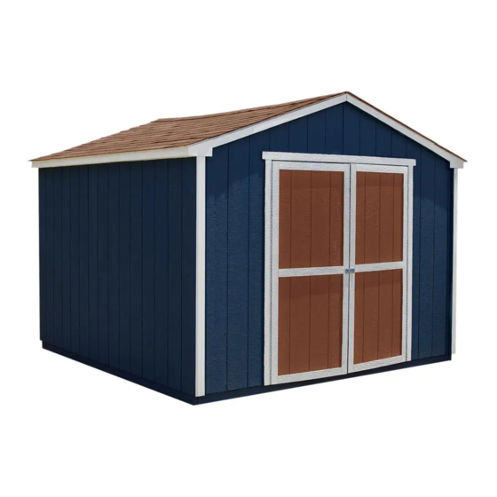
16757 05/28/2013 ASSEMBLY MANUAL A Backyard Products Company MARCO SERIES PRINCETON 10' x 10' (305 x 305 cm) ACTUAL FLOOR SIZE IS 120 x 116-5/8" (305 x 296 cm) KEEP THIS MANUAL FOR FUTURE REFERENCE IMPORTANT! READ INSTRUCTIONS THOROUGHLY PRIOR TO BEGINNING ASSEMBLY. - Page 4 TOOLS Required Optional ❑ Phillips ❑ Tool Belt/ ❑ Utility Knife Screwdriver Nail Pouch ❑ Shingle Blades ❑ Drill / Driver ❑ Tin Snips ❑ 3/8" Drill Bit ❑ Caulk Gun (for drip edge) ❑ #2 Philips Drive Bit ❑ Chalk Line ❑...
-
Page 5: Additional Materials
ADDITIONAL MATERIALS FOUNDATION OR FLOOR MATERIALS • This shed kit includes a complete wood Á oor frame system. It does not include any Á oor panels. • See page 6 for the additional Á oor panel sizes and quantities required. •... -
Page 6: Parts List
PARTS IDENTIFICATION AND SIZES Part identiÀ cation WOOD SIZE CONVERSION CHART Treated lumber is stamped: is stamped on some parts. Nominal Board Size Actual Size 2" x 4"....1-1/2" x 3-1/2" (3,8 x 8,9 cm) 1" x 4"....3/4" x 3-1/2" (1,9 x 8,9 cm) 2"... - Page 7 WALL PANEL & DOORS PARTS LIST 3/8 x 23-7/8 x 72" 3/8 x 48 x 72" LEFT DOOR RIGHT DOOR (1 x 61 x 183 cm) (1 x 122 x 183 cm) ROOF PANELS 23-7/8 x 19" 19" x 96" (61 x 48 cm) (48 x 244 cm) 23-7/8 x 48"...
- Page 8 FLOOR PANELS (Not Included) You will need Á oor panels and nails to complete your Á oor. -Floor panel sizes and quantities are shown below. NOTE: Use a minimum of 5/8" (1,6 cm) oriented strand board (OSB). 23-7/8 x 23-7/8" (61 x 61 cm) 23-7/8 x 92-5/8"...
- Page 9 FLOOR LEVELING OPTIONS There are multiple ways to level your Û oor frame. Our recommended leveling method is shown below. Leveling materials are not included in this kit. PREFERRED METHOD - 4x4 TREATED RUNNERS Support seam. 4x4 Runners (not included). 8"...
- Page 10 CONCRETE FOUNDATION Your kit contains all materials to construct a wooden Û oor. If you choose to install your kit on a concrete slab refer to the diagram below. Treated Sill Plate Caulk between sill plate and concrete. 3-1/2" (8,9 cm) 4"...
- Page 11 FLOOR FRAME PARTS REQUIRED: 3" (7,6 cm) x28 TREATED 2 x 4 x 72" (5 x 10 x 183 cm) TREATED NOTE: 2 x 4 x 48" (5 x 10 x 122 cm) Look for Stamp. TREATED 2 x 4 x 21" (5 x 10 x 53 cm) You will build two Á...
- Page 12 FLOOR FRAME PARTS REQUIRED: 3" (7,6 cm) x28 TREATED 2 x 4 x 72" (5 x 10 x 183 cm) Treated Wood TREATED 2 x 4 x 89-1/2" (5 x 10 x 227 cm) Treated Wood NOTE: TREATED Look for Stamp.
- Page 13 FLOOR FRAME 3" (7,6 cm) x40 Put both Á oor sections together and attach as shown using 3" nails. FINISH You have À nished your Á oor frame. Proceed to level and square frame. (4) Nails per side, stagger pattern. 120"...
- Page 14 FLOOR PANELS PARTS REQUIRED: FLOOR PANELS NOT INCLUDED. 2" (5 cm) x55 SEE PAGE 6 FOR PANEL SIZES AND QUANTITIES. 5/8 x 48 x 92-5/8" (1,6 x 122 x 235 cm) Ensure your Á oor frame is square by installing one panel and squaring frame. BEGIN Attach the 48 x 92-5/8"...
- Page 15 FLOOR PANELS PARTS REQUIRED: 5/8 x 23-7/8 x 23-7/8" (1,6 x 61 x 61 cm) 2" (5 cm) x154 5/8 x 23-7/8 x 92-5/8" (1,6 x 61 x 235 cm) 5/8 x 23-7/8 x 96" (1,6 x 61 x 244 cm) 5/8 x 48 x 92-5/8"...
- Page 16 IMPORTANT! I M P O R T A N T ! Check the Á oor frame is level after installing Á oor panels. Re-level if needed. • The Á oor should used as a stable work surface for wall construction. HINT: •...
- Page 17 RAFTER ASSEMBLY JIG PARTS REQUIRED: 1-1/4" (3,2 cm) x8 3/4 x 3 x 5" (1,9 x 7,6 x 12,7 cm) 3/4 x 3 x 8-1/2" (1,9 x 7,6 x 21,6 cm) ¸ BEGIN Build a Jig to ensure all Rafters are assembled the same. Mark a straight line on the Floor from corner to corner.
- Page 18 RAFTERS PARTS REQUIRED: 2" (5 cm) x96 6 x 24" (15 x 61 cm) 2 x 4 x 65-7/8" (5 x 10 x 167 cm) ¸ BEGIN Place two rafter halves CV on Á oor jig. You will assemble (4) rafters. Rafters should touch at peak.
- Page 19 BACK WALL FRAME PARTS REQUIRED: 3" (7,6 cm) x6 2 x 3 x 46-1/4" (5 x 7,6 x 117,5 cm) 2 x 3 x 77" (5 x 7,6 x 196 cm) 2 x 3 x 94-1/2" (5 x 7,6 x 240 cm) BEGIN Orient parts on edge on Á...
- Page 20 BACK WALL FRAME PARTS REQUIRED: 3" (7,6 cm) x2 2 x 3 x 46-1/4" (5 x 7,6 x 117,5 cm) Orient parts on edge on Á oor as shown. Use two 3" screws at middle connection. FINISH You have À nished building your back wall frame. 48-3/4"...
- Page 21 BACK WALL PANELS PARTS REQUIRED: 2" (5 cm) x33 3/8 x 48 x 96" (1 x 122 x 244 cm) 3/4" GAUGE BLOCK BEGIN Place LEFT panel on back frame as shown with primed side facing up. Use a 3/4" gauge block at edges of panel. Be sure to maintain 1"...
- Page 22 BACK WALL PANELS PARTS REQUIRED: 2" (5 cm) x33 3/8 x 48 x 96" (1 x 122 x 244 cm) 3/4" GAUGE BLOCK Place RIGHT panel on back frame as shown with primed side facing up. Use a 3/4" gauge block at edges of panel. Nail using 2"...
- Page 23 WING WALL PANELS PARTS REQUIRED: 1-1/4" (3 cm) x32 RIGHT LEFT 2 x 3 x 72" (5 x 7,6 x 183 cm) BEGIN You will assemble TWO RIGHT and TWO LEFT wing walls. Place OY Place a wing wall panel primed side down onto OY oor.
- Page 24 BACK WALL PANELS PARTS REQUIRED: 2" (5 cm) x24 Pre-assembled LEFT Pre-assembled RIGHT Place wing wall assemblies onto frame with bottom of panels Á ush. Nail left and right wing wall assemblies onto back wall frame using 2" nails 6" apart. Do not nail in groove.
- Page 25 FRONT WALL FRAME PARTS REQUIRED: 3" (7,6 cm) x6 2 x 3 x 22-1/8" (5 x 7,6 x 56 cm) 2 x 3 x 77" (5 x 7,6 x 196 cm) 2 x 3 x 94-1/2" (5 x 7,6 x 240 cm) BEGIN Lay out two PB, one PR and one LT on edge on Á...
- Page 26 FRONT WALL PANELS PARTS REQUIRED: 2" (5 cm) x22 3/4" GAUGE 3/8 x 48 x 96" BLOCK (1 x 122 x 244 cm) BEGIN Place LEFT panel on front frame as shown with primed side up. Use a 3/4" gauge block on edges of panel.Be sure to maintain 1" measurement between bottom edge of frame and bottom edge of panel (Fig.
- Page 27 FRONT WALL PANELS PARTS REQUIRED: 2" (5 cm) x22 3/8 x 48 x 96" (1 x 122 x 244 cm) 3/4" GAUGE BLOCK Place RIGHT panel on front frame primed side up. Use a 3/4" gauge block on edges of panel. Nail panel to frame with 2"...
- Page 28 FRONT WALL PANELS PARTS REQUIRED: 2" (5 cm) x24 Pre-assembled LEFT Pre-assembled RIGHT Place wing wall panels onto frame with bottom of panels Á ush. Nail left and right wing wall assemblies using 2" nails 6" apart. Do not nail in groove.
- Page 29 SIDE WALL FRAMES PARTS REQUIRED: 3" (7,6 cm) x18 2 x 3 x 46-1/4" (5 x 7,6 x 117,5 cm) 2 x 3 x 69" (5 x 7,6 x 175 cm) 2" x 3" x 70-1/4" (5 x 7,6 x 178,4 cm) 7/16 x 2-1/2 x 73-1/2"...
- Page 30 SIDE WALL FRAME- SOFFIT PARTS REQUIRED: 1-1/4" (3,2 cm) x28 3/8 x 5 x 21-1/4" (0,9 x 12,7 x 54 cm) 3/8 x 5 x 96" (0,9 x 12,7 x 244 cm) Place panels onto 2x3 with primed side against 2x3 (Fig A). Keep panels Á...
- Page 31 SIDE WALL PANELS PARTS REQUIRED: 2" (5 cm) x34 3/4" GAUGE BLOCK 3/8 x 48 x 72" (1 x 122 x 183 cm) Ensure your wall frame is square by installing one panel and squaring frame. Place the 48 x 72" panel onto wall frame with primed side up as shown. Note the lip and square edges.
- Page 32 SIDE WALL PANELS PARTS REQUIRED: 2" (5 cm) x166 3/8 x 23-7/8 x 72" (1 x 61 x 183 cm) 3/8" x 48" x 72" 3/4" GAUGE (1 x 122 x 183 cm) BLOCK For squareness maintain 3/4" and Á ush under sofÀ t panel. To draw panels tight at seams angle nail.
-
Page 33: Back Wall Installation
BACK WALL INSTALLATION PARTS REQUIRED (TEMPORARY): 3" (7,6 cm) x8 2 x 3 x 69" (5 x 7,6 x 175,3 cm) 2" (5 cm) x24 BEGIN Center back wall assembly on the 120" (305 cm) Á oor dimension. Use OO as a temporary brace. Secure with two 3" screws. 3"... - Page 34 SIDE WALLS INSTALLATION 3" (7,6 cm) x4 3" (7,6 cm) x16 2" (5 cm) x70 BEGIN Stand right sidewall on Á oor. It is important to secure the sidewall in the following order. SofÀ t Panel Center sidewall on ¹ oor front to back.
- Page 35 FRONT WALL INSTALLATION 3" (7,6 cm) x8 2" (5 cm) x38 BEGIN Stand frontwall on Á oor. It is important to secure the frontwall in the following order. SofÀ t 3/8" (0,9 cm) OVERLAP Panel Center frontwall on Á oor side-to-side. Trim Panel The sidewall sofÀ...
- Page 36 GABLE TRIM PARTS REQUIRED: 1-1/4" (3 cm) x24 2 x 3 x 54-5/16" (5 x 7,6 x 138 cm) ¸ BEGIN Position one CD Á ush to front panel edge and center on right edge of groove (Fig. A). Attach trim with eight 1-1/4" screws from inside. Install two screws at seam (Fig.
- Page 37 TRIM / ENDCAPS PARTS REQUIRED: 1-1/4" (3,2 cm) x32 3/4 x 3-1/2 x 5" (1,9 x 9 x 12,7 cm) 3/4 x 3-1/2 x 8-1/2" (1,9 x 9 x 21,6 cm) RIGHT PAINTED RED 3/4 x 6-1/4 x 11-7/8" (1,9 x 15,8 x 30 cm) LEFT PAINTED GREEN ¸...
- Page 38 RAFTERS PARTS REQUIRED: pre-assembled 3" (7,6 cm) x16 2" (5 cm) x8 ¸ BEGIN Locate rafters directly over studs and Á ush to overhang in wall frame (Fig. A). Check that you have the measurements shown. Screw through sofÀ t panel into rafters using one 2"...
- Page 39 TRIM PARTS REQUIRED: 2" (5 cm) x28 1 x 3 x 23-1/4" (2,5 x 7,6 x 59 cm) 1 x 3 x 95-1/2" (2,5 x 7,6 x 242,5 cm) ¸ BEGIN Attach fascia trim Á ush to bottom of sofÀ t (Fig. A) and endcaps at ends of rafters (Fig.
- Page 40 ROOF PANELS PARTS REQUIRED: 2" (5 cm) x152 3/4" GAUGE 7/16 x 19 x 96" 7/16 x 48 x 96" BLOCK (1,1 x 48 x 244 cm) (1,1 x 122 x 244 cm) 7/16 x 23-7/8 x 48" 7/16 x 23-7/8 x 19" (1,1 x 61 x 122 cm) (1,1 x 61 x 48 cm) Roof panels may cause serious injury...
- Page 41 ROOF PANELS PARTS REQUIRED: 3/4" GAUGE BLOCK Flush Keep spacing between the center of the rafters at the lower edge of the 7/16 x 23-7/8 x 48" panel and secure with one 2" nail into (1,1 x 61 x 122 cm) each rafter (Fig.
- Page 42 DOORS PARTS REQUIRED: 1-1/4" (3 cm) x2 2 x 3 x 69" (5 x 7,6 x 175,3 cm) 2" (5 cm) x2 HINT: Look for 3/8" SPACER 3" (7,6 cm) x4 attached to doors. 5/8 x 3 x 72" (1,6 x 7,6 x 183 cm) Left Door Right Door BEGIN...
- Page 43 DOORS PARTS REQUIRED: 3" (7,6 cm) x7 2 x 3 x 69" (5 x 7,6 x 175,3 cm) Attach temporary support OO as a ledger board Á ush under wall panels for doors to rest on, using three 3" screws (Fig. A). Flush against wall panels.
- Page 44 DOOR PARTS REQUIRED: 2" (5 cm) x8 3/4" (1,9 cm) x52 5/8 x 3 x 72" (1,6 x 7,6 x 183 cm) BEGIN Secure hinge boards from inside using 3/4" screws as shown (Fig. A). Reinforce the door trim using 3/4" screws through door panel into trim (Fig. A). Locate screws as shown in Fig.
- Page 45 DOOR WEATHERSTRIP PARTS REQUIRED: 2" (5 cm) x14 2 x 3 x 69" (5 x 7,6 x 175 cm) BEGIN With left door closed, center a weatherstrip OO vertically on the left door in the door opening (Fig. A). OO will offset the left door 1" OUT past the door trim 1"...
-
Page 46: Door Hardware
DOOR HARDWARE PARTS REQUIRED: 3/8" (9 mm) Drill Bit 3/4" (1,9 cm) x4 3/4" (1,9 cm) x7 BEGIN Mount barrel bolt Á ush at top of OO on left door using 3/4" screws as shown (Fig A). With door closed mark hole location for bolt to extend into. HINT: Extend bolt to leave a mark in wood. - Page 47 PAINT & CAULK - NOT INCLUDED - • Use acrylic latex caulk that is paintable. Caulk at all horizontal and vertical seams, between the trim and walls, and all around the door trim. • Use a high quality exterior acrylic latex paint. When painting your building, there are a few key areas that can be easily overlooked that must be painted: •...
- Page 48 SHINGLES - NOT INCLUDED - • Follow directions provided by manufacturer and these instructions. Familiarize yourself with a 3-Tab Shingle. Notch Notch SHINGLE NAIL PATTERN 1/2" 1" Sealing Strip 1" (1,3 cm) (2,5 cm) (2,5 cm) Half A Rain Slot Full Rain Slot NAILS NEVER DRIVE FASTENERS INTO OR ABOVE SEALING STRIPS.
- Page 49 SHINGLES continued... Beginning at front of shed, install À rst row of shingles with notch at 1" past roof edge or Á ush with drip edge. Roof Deck FRONT OF BACK OF SHED SHED 1" (2,5 cm) Flush with starter row. Notch - or - Drip Edge...
- Page 50 SHINGLES continued... Continue installing rows of shingles to the peak. At the peak make sure there is a maximum of 5" or less to the rain slot, as shown below. If shingles overlap at ridge cut to peak with a utility knife. 5"...
- Page 51 SHINGLES - RIDGE CAP • You will À nish off the top of the roof with a ridge cap made from shingles. BEGIN Cut shingles into THREE pieces. Hint: Use cut-off pieces À rst. 2" 2" (5 cm) (5 cm 2"...
- Page 52 SHINGLES - RIDGE CAP continued... Continue installing ridge cap to back of roof. Make sure there is 4" between the shingle-color and edge of shingles. 4" (10 cm) Trim cap off Á ush to shingles When you have 4" minimum of shingle color cut one piece to cap your roof. Cut at top of rain slot.
- Page 53 WARRANTY Backyard Storage Solutions, LLC warrants the following: Limited Conditional Every product is warranted from defects in workmanship and manufacturing for one year. Warranty * All hardware and metal components are warranted for two years. Trim is warranted for 10 years. Waferboard siding and sheathing is warranted for two years.
Need help?
Do you have a question about the HANDY HOME PRODUCTS MARCO Series and is the answer not in the manual?
Questions and answers