Table of Contents
Advertisement
Quick Links
For questions on assembly or for general inquiries, you may contact us in the following ways:
Call a Recruiter Today! 734-365-7000
Flexible schedule
*based on number of completed installations
Call Us First!
DO NOT RETURN TO STORE.
Call customer service: 1-877-743-3400
AVOID THE WAIT!
visit us online at
help.backyardproducts.com
Submit a help request
Answers to frequently asked questions
Live chat with an agent
Did you enjoy building your shed?
JOIN OUR TEAM
AND MAKE UP TO $1,500/WEEK*
No selling,
just building
Bonus incentives
available
16916-W
Advertisement
Table of Contents

Related Manuals for Backyard Products MODERN 12 x 7


Summary of Contents for Backyard Products MODERN 12 x 7
- Page 1 16916-W Call Us First! DO NOT RETURN TO STORE. For questions on assembly or for general inquiries, you may contact us in the following ways: Call customer service: 1-877-743-3400 AVOID THE WAIT! visit us online at help.backyardproducts.com Submit a help request Answers to frequently asked questions Live chat with an agent Did you enjoy building your shed?
- Page 2 (This page intentionally left blank.)
-
Page 3: Assembly Manual
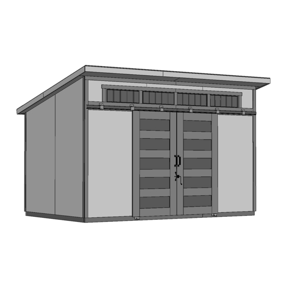
16916-W 03/26/2021 ASSEMBLY MANUAL MODERN 12' x 7'-6" (365,8 x 228,6 cm) ACTUAL FLOOR SIZE IS 144" x 90" (365,8 x 228,6 cm) KEEP THIS MANUAL FOR FUTURE REFERENCE IM P O RTANT ! READ INSTRUCTIONS THOROUGHLY PRIOR TO BEGINNING ASSEMBLY. BEFORE YOU BEGIN •... - Page 4 TOOLS Required Optional Phillips Tool Belt/ ❑ ❑ Utility Knife ❑ Screwdriver Nail Pouch Shingle Blades ❑ Drill / Driver ❑ Tin Snips 1/4" Drill Bit ❑ ❑ (for drip edge) Caulk Gun ❑ 3/8" Drill Bit ❑ 1/2" Drill Bit ❑...
-
Page 5: Additional Materials
ADDITIONAL MATERIALS FOUNDATION OR FLOOR MATERIALS • This shed kit includes a complete wood floor system. • This shed kit does not include ANY leveling materials. • See the FLOOR LEVELING section on page 8 for recommended methods and suggested materials to properly level your foor, as this will vary depending on your specific site. -
Page 6: Parts List
PARTS IDENTIFICATION AND SIZES Part identification WOOD SIZE CONVERSION CHART letters are stamped on some parts. Treated lumber is stamped: Nominal Board Size Actual Size 2 x 4 ....1-1/2" x 3-1/2" (3,8 x 8,9 cm) 1 x 4 ....3/4" x 3-1/2" (1,9 x 8,9 cm) 2 x 3 ....1-1/2"... - Page 7 PARTS LIST continued... 19/32" x 3-1/2" x 59-1/4" (1,5 x 8,8 x 150,4 cm) 19/32" x 3-1/2" x 60-1/2" (1,5 x 8,8 x 153,7 cm) 19/32" x 3-1/2" x 61-1/16" (1,5 x 8,8 x 155,1 cm) 19/32" x 3-1/2" x 61-1/16" (1,5 x 8,8 x 155,1 cm) 19/32 x 2-1/2 x 67-3/4"...
- Page 8 WALL PANEL & DOORS PARTS LIST 3/8" x 10-7/16" x 48" (1 x 26,5 x 121,9 cm) 3/8" x 4-1/2" x 48" 3/8" x 48 x 76" 3/8" x 48" x 84" 3/8" x 48" x 84" (1 x 11,4 x 121,9 cm) (1 x 113,3 x 193 cm) (1 x 122 x 213,4 cm) (1 x 122 x 213,4 cm)
-
Page 9: Door Hardware
HARDWARE / WINDOWS / Misc. H 2.5 Tie Plate 1/2" (1,2 cm) 8 x 16" Window (20,3 x 35,6 cm) DOOR HARDWARE #12 2" (5,1 cm) 2" (5,1 cm) 1-1/2" (3,8 cm) Spring Door Bolt Stop 1-1/4" (3,2 cm) #8 3/4" (1,9 cm) 1"... - Page 10 FLOOR LEVELING OPTIONS There are multiple ways to level your floor frame. Our recommended leveling method is shown below. Leveling materials are not included in this kit. PREFERRED METHOD - 4x4 TREATED RUNNERS • 3" Screws angled into 4x4. • (2) at each point frame •...
- Page 11 CONCRETE FOUNDATION Your kit contains all materials to construct a wooden floor. If you choose to install your kit on a concrete slab refer to the diagram below. Treated Sill Plate Caulk between sill plate and concrete. 3-1/2" (8,9 cm) 4"...
-
Page 12: Parts Required
FLOOR FRAME PARTS REQUIRED: 3" (7,6 cm) 2 x 4 x 87" (5,1 x 10,2 x 221 cm) Look for TREATED 2 x 4 x 96" (5,1 x 10,2 x 243,8 cm) Stamp 2 x 4 x 48" (5,1 x 10,2 x 121,9 cm) BEGIN Orient parts as shown on flat surface. - Page 13 LEVEL AND SQUARE FLOOR FRAME Before attaching floor decking, it is important to level and square the floor frame. A level and square floor frame is required to correctly construct your shed. BEGIN See page 8 for the preferred floor leveling method. Use level and check the frame is level before applying floor panels.
- Page 14 FLOOR PANELS PARTS REQUIRED: 2" (5,1 cm) 5/8" x 48" x 96" (1,6 x 121,9 x 243,8 cm) BEGIN Attach the 5/8" x 48" x 96" panel with the rough side up (painted-grid lines side) and with the 48" edge and corner flush to the floor frame (Fig A). Secure panel with (2) 2"...
- Page 15 FLOOR PANELS PARTS REQUIRED: x123 2" (5,1 cm) 5/8" x 42" x 96" 5/8" x 48" x 90" (1,6 x 106,7 x 243,8 cm) (1,6 x 60,6 x 122 cm) Continue installing panels with 2" nails spaced 6" apart on edges, and 12" apart inside panels. Flush 6"...
- Page 16 IMPORTANT! Check the foor frame is level after installing foor panels. Re-level if needed. • The foor should be used as a stable work surface for wall construction. • Organize your assembly procedure during the build process HINT: to avoid over-handling of the walls. Back Wall Front Wall...
- Page 17 BACK WALL FRAME PARTS REQUIRED: 3" (7,6 cm) 2 x 4 x 48" (5,1 x 10,2 x 121,9 cm) 2 x 4 x 68" (5,1 x 10,2 x 172,7 cm) 2 x 4 x 96" (5,1 x 10,2 x 243,8 cm) BEGIN Orient parts on edge on floor.
- Page 18 BACK WALL PANELS PARTS REQUIRED: 2" (5,1 cm) 3/4" GAUGE 48" x 76" BLOCK (121,9 x 193 cm) • Ensure top of panel is overhanging the top of frame by 4". Place 48" x 76" panel onto wall frame with primed side up as shown. Use the gauge block to mark the 3/4"...
- Page 19 BACK WALL PANELS PARTS REQUIRED: 2" (5,1 cm) 3/4" GAUGE BLOCK 48" x 76" (121,9 x 193 cm) Place center and end 48" x 76" panels For squareness maintain 3/4" on frame as shown (Fig. A, Fig. B). measurement along panel edges. Flush Secure panel with 2"...
- Page 20 FRONT WALL - DOOR HEADER PARTS REQUIRED: 3" (7,6 cm) 7/16" x 3-1/4" x 66-3/4" (1,1 x 8,3 x 169,5 cm) 2" (5,1 cm) 2 x 4 x 67" (5,1 x 10,2 x 170,2 cm) BEGIN Build header assembly as shown using 3" and 2" nails. Flush 3"...
- Page 21 FRONT WALL FRAME PARTS REQUIRED: 3" (7,6 cm) 2 x 4 x 40" (5,1 x 10,2 x 101,6 cm) 2 x 4 x 70-1/2" (5,1 x 10,2 x 179,1 cm) 2 x 4 x 12-1/8" (5,1 x 10,2 x 30,8 cm) 2 x 4 x 72"...
- Page 22 FRONT WALL FRAME PARTS REQUIRED: Pre-Assembled Door Header 3" (7,6 cm) 4" x 67" (170,2 cm) 2 x 4 x 68-9/16" (5,1 x 10,2 x 174,1 cm) Install door header with OSB to the top of header. Secure header with 3" nails at locations shown. Orient parts NCE on edge as shown.
- Page 23 FRONT WALL PANELS PARTS REQUIRED: 2" (5,1 cm) 3/8" x 48" x 96" (1 x 121,9 x 243,8 cm) Install all panels with the primed side facing up. Handle panels with care to avoid breakage. BEGIN Install first 48" x 96" panel 5-7/8" above top plate. Secure panel with 2"...
- Page 24 FRONT WALL PANELS PARTS REQUIRED: 2" (5,1 cm) 3/8" x 1-1/2" x 9" (1 x 3,8 x 22,9 cm) 3/8" x 4-1/2" x 48" 3/8" x 10-7/16" x 48" (1 x 11,4 x 121,9 cm) (1 x 26,5 x 121,9 cm) Install panels in the following order: 1.
- Page 25 FRONT WALL PANELS PARTS REQUIRED: 3" (7,6 cm) 2" (5,1 cm) Temporary Brace 2 x 3 x 72" (5,1 x 7,6 x 182,8 cm) 3/8" x 48" x 96" (1 x 121,9 x 243,8 cm) Install 2nd 48" x 96" panel flush to frame as shown and 5-7/8" from the top. Secure panel with 2"...
-
Page 26: Back Wall Installation
BACK WALL INSTALLATION PARTS REQUIRED: 3" (7,6 cm) TEMPORARY 2 x 3 x 59-1/4" (5,1 x 7,6 x 150,5 cm) 3" (7,6 cm) 2" (5,1 cm) BEGIN Center back wall assembly on the 144" floor dimension. Note: The 4" wall overhang is installed to the top. 4"... - Page 27 FRONT WALL INSTALLATION PARTS REQUIRED 3" (7,6 cm) TEMPORARY 2 x 4 x 78-1/16" (5,1 x 10,2 x 198,3 cm) 3" (7,6 cm) 2" (5,1 cm) BEGIN Center front wall assembly on the 144" front floor dimension. Use (2) OFB as temporary braces. Level wall and secure OFB with 3"...
- Page 28 DOUBLER INSTALLATION PARTS REQUIRED: 3" (7,6 cm) 2 x 4 x 48" (5,1 x 10,2 x 122 cm) 2 x 4 x 96" (5,1 x 10,2 x 243,8 cm) BEGIN Center doublers SP and TP on back wall top plate. Secure using 3"...
- Page 29 OUTER RAFTER INSTALLATION PARTS REQUIRED: 3" (7,6 cm) 2 x 4 x 92-3/16" (5,1 x 10,2 x 234,2 cm) 2" (5,1 cm) BEGIN Install rafters on front and back wall doublers. Ensure rafters are flush to end of top plates (Fig. B, Fig. D). Secure rafters as shown in all Figures.
- Page 30 OUTER RAFTER INSTALLATION PARTS REQUIRED: H 2.5 Tie Plate 1-1/2" (3,8 cm) Attach tie plates using 1-1/2" nails as shown. 1-1/2" (3,8 cm) Nails FINISH Your outer rafters are now installed.
- Page 31 RAFTERS PARTS REQUIRED: 3" (7,6 cm) 2 x 4 x 92-3/16" (5,1 x 10,2 x 234,2 cm) 2" (5,1 cm) BEGIN Measure and mark location of each rafter. Note the door location. Center rafters on marks. Secure rafters using 2" screws installed centered into outer rafter ends (Fig. A). Continue securing rafters using 3"...
- Page 32 RAFTERS PARTS REQUIRED: H 2.5 Tie Plate 1-1/2" (3,8 cm) Attach (9) tie plates using 1-1/2" nails as shown (Fig. A). Fig. A 1-1/2" (3,8 cm) Nails FINISH Your rafters are now installed.
- Page 33 SIDE WALL PANELS PARTS REQUIRED: 3" (7,6 cm) TEMPORARY SUPPORT 1-1/4 x 2-1/2 x 69" (3,2 x 6,3 x 175,3 cm) 2" (5,1 cm) 1-1/2" (3,8 cm) 3/8" x 42" x 96" 3/8" x 42" x 96" 3/8" x 48" x 84" 3/8"...
- Page 34 SIDE WALL PANELS PARTS REQUIRED: 1-1/2" (3,8 cm) 2" (5,1 cm) Place 48" x 84" panel onto side wall flush with bottom of installed 42" x 96" panel. Secure panel with (1) 2" nail in bottom corner (Fig. C). Ensure the measurement between the panel edges are the same along the corner (Fig.
- Page 35 SIDE WALL STUDS PARTS REQUIRED: 3" (7,6 cm) 2 x 4 x 78-1/16" (5,1 x 10,2 x 198,3 cm) 2 x 4 x 82-1/2" (5,1 x 10,2 x 209,6 cm) 2 x 4 x 86-15/16" (5,1 x 10,2 x 220,8 cm) BEGIN Install NES centered at seam of side wall panels (Fig A).
- Page 36 SIDE WALL PANELS PARTS REQUIRED: 1-1/2" (3,8 cm) (Left / Green) (Right / Red) 3/8" x 2-11/16" x 12-1/4" (1,5 x 6,8 x 31,1 cm) 3/8" x 2-11/16" x 12-1/4" (1,5 x 6,8 x 31,1 cm) BEGIN Install 2-11/16" x 12-1/4" triangular filler panel with (2) 1-1/2" nails. Flush filler panel to installed panels (Red for right side) as shown.
- Page 37 ROOF PANELS PARTS REQUIRED: 2" (5,1 cm) 7/16 x 10-11/16 x 28" (1,1 x 27,1 x 71,1 cm) 7/16 x 10-11/16 x 96" 3/4" GAUGE (1,1 x 27,1 x 243,8 cm) 7/16 x 10-11/16 x 31-7/8" BLOCK (1,1 x 27,1 x 81 cm) Roof panels may cause serious injury until securely fastened.
- Page 38 ROOF PANELS PARTS REQUIRED: 2" (5,1 cm) 3/4" GAUGE 7/16" x 48 x 96" BLOCK (1,1 x 121,9 x 243,8 cm) Square the roof by attaching one 48" x 96" panel at this time. Use the panel's long edge as a lever to bring your roof into square. Place the 48"...
- Page 39 ROOF PANELS PARTS REQUIRED: 2" (5,1 cm) 3/4" GAUGE 7/16" x 48" x 96" BLOCK 7/16" x 11-7/8" x 96" (1,1 x 121,9 x 243,8 cm) (1,1 x 30,2 x 243,8 cm) Install 2nd 48"x 96" panel flush to installed panels. Maintain 3/4"...
- Page 40 ROOF PANELS PARTS REQUIRED: x160 2" (5,1 cm) Complete the securing of all upper roof panels with 2" nails 6" along edge and 12" inside panel. 6" (15,2 cm) FINISH Your roof panels are now installed.
- Page 41 RAFTER EXTENSIONS PARTS REQUIRED: 2" (5,1 cm) 2 x 3 x 10-7/16" (5,1 x 7,6 x 26,5 cm) BEGIN Line up each rafter extension QVA 90 degrees square with rafters as shown. Secure rafter extensions with 2" screws through roof panels (Fig. A). Use (4) screws at roof panel seams.
- Page 42 SIDE RAKE FRAMING PARTS REQUIRED: 2" (5,1 cm) 1 x 3 x 31-15/16" (2,5 x 7,6 x 81,1 cm) 1 x 3 x 72" (2,5 x 7,6 x 182,8 cm) BEGIN Align THB edge flush with rafter extension (Fig A). Attach with (3) 2" nails (Fig B). Attach HJ flush with THB with (5) 2"...
- Page 43 SIDE SOFFIT PARTS REQUIRED: 2" (5,1 cm) 3/8" x 5-1/4" x 94-7/16" (1 x 13,3 x 242,5 cm) BEGIN Attach 94-7/16" soffit primed side down flush to front wall panel (Fig. A). Secure to side rake frame THB using (7) 2" finish nails (Fig. A, B). Fig.
- Page 44 FRONT SOFFIT PARTS REQUIRED: 2" (5,1 cm) 3/8" x 10-3/8" x 75-5/8" (1 x 26,3 x 191,2 cm) 3/8" x 10-3/8" x 79-5/8" (1 x 26,3 x 202,2 cm) BEGIN Install 75-5/8" and 79-5/8" soffit panel primed side out under rafter extensions and flush to side wall soffit (Fig.
-
Page 45: Front Wall
FRONT FASCIA TRIM PARTS REQUIRED: 2" (5,1 cm) 19/32" x 3-1/2" x 60-1/2" (1,5 x 8,8 x 153,7 cm) BEGIN Measure 1/4" past left roof panel and line up WAB primed side out and flush up under roof panels (Fig. A). Right side of WAB is approximately 3/4" from center of rafter extension. Secure WAB with 2"... - Page 46 FRONT FASCIA TRIM PARTS REQUIRED: 2" (5,1 cm) 19/32" x 3-1/2" x 96" (1,5 x 8,8 x 243,8 cm) Position ZX primed side out, flush with WAB and flush up under roof panels. Secure ZX with 2" finish nails into rafter extensions (Fig. B). 2"...
- Page 47 SIDE FASCIA TRIM ASSEMBLY PARTS REQUIRED: 2" (5,1 cm) 2 x 3 x 31-15/16" (5,1 x 7,6 x 81,1 cm) 19/32" x 3-1/2" x 61-1/16" (1,5 x 8,9 x 155,1 cm) 19/32" x 3-1/2" x 45" (1,5 x 8,9 x 114,3 cm) 19/32"...
- Page 48 SIDE FASCIA TRIM PARTS REQUIRED: 2" (5,1 cm) 2" (5,1 cm) LEFT FASCIA ASSEMBLY BEGIN Place left side fascia assembly between roof sheathing and side soffit (Fig. A, Fig. B). Secure fascia assembly under roof panels flush with front fascia board using (6) 2" screws through roof sheathing (Fig.
- Page 49 SIDE FASCIA TRIM PARTS REQUIRED: 2" (5,1 cm) RIGHT FASCIA ASSEMBLY Nail up through side soffit into fascia assembly using (7) 2" finish nails (Fig. C). Secure front fascia to side fascia with (2) 2" finished nails (Fig. D). 2" Finish Nails FRONT WALL...
- Page 50 REAR FASCIA TRIM PARTS REQUIRED: 3" (7,6 cm) 2 x 3 x 59-1/4" (5,1 x 7,6 x 150,5 cm) 2" (5,1 cm) 2 x 3 x 96" (5,1 x 7,6 x 243,8 cm) BEGIN Install PT and GKA using 2" wood screws through roof sheathing (Fig. A). 2"...
- Page 51 REAR FASCIA TRIM PARTS REQUIRED: 2" (5,1 cm) 19/32" x 3-1/2" x 59-1/4" (1,5 x 8,8 x 150,5 cm) 19/32" x 3-1/2" x 96" (1,5 x 8,8 x 243,8 cm) Secure HBA and ZX to PT and GKA with 2" finish nails (Fig. C). Ensure trim is primed side out.
- Page 52 BACK CORNER TRIM PARTS REQUIRED: 2" (5,1 cm) 3/8" x 2" x 73-5/16" (0,9 x 5,1 x 186,2 cm) ¸ BEGIN Place 73-5/16" back corner trim flush to bottom of back soffit board (Fig. A) and flush with side panel (Fig. B). Secure trim with (14) 2"...
- Page 53 SIDE CORNER TRIM PARTS REQUIRED: 2" (5,1 cm) 3/8" x 2" x 73-7/16" (0,9 x 5,1 x 186,5 cm) 3/8" x 2" x 73-7/16" (0,9 x 5,1 x 186,5 cm) 3/8" x 2" x 93-1/8" (0,9 x 5,1 x 236,5 cm) 3/8"...
- Page 54 FRONT TRIM PARTS REQUIRED: 2" (5,1 cm) 19/32" x 2-1/2" x 72-3/4" (1,5 x 6,3 x 184,8 cm) 19/32" x 2-1/2" x 90-5/8" (1,5 x 6,3 x 230,2 cm) ¸ BEGIN Install (2) ZD trim pieces centered and flush up to soffit. Secure trim with (14) 2"...
- Page 55 FRONT WINDOWS PARTS REQUIRED: 3/4" (1,9 cm) ¸ BEGIN Apply high quality exterior-grade caulk behind frame near edge before installing to seal window. You must caulk around windows to validate warranty. Position window in center of opening and level. Secure with (4) screws on sides of each window. (4) 3/4"...
- Page 56 FRONT WINDOW TRIM PARTS REQUIRED: 2" (5,1 cm) 19/32" x 2-1/2" x 9" (1,5 x 6,4 x 22,9 cm) 19/32" x 5-1/2" x 70-1/4" (1,5 x 14 x 178,4 cm) Install (2) CMB centered on front wall panels. Install CMB 1" (2,5 cm) below bottom panel, across door opening. Secure with (18) 2"...
- Page 57 FRONT WINDOW TRIM PARTS REQUIRED: 3/4" (1,9 cm) 19/32" x 2-1/2" x 58-3/4" (1,5 x 6,3 x 149,2 cm) Install (2) TTB on window trim, centered as shown. Secure with (6) 2" finish nails. 2" (5,1 cm) Finish Nails Nail into FRAMING Flush CENTER...
- Page 58 DOOR TRIM &THRESHOLD PARTS REQUIRED: 2" (5,1 cm) 64" Metal Threshold 19/32 x 2-1/2 x 67-3/4" (1,5 x 6,3 x 172,1 cm) 3/4" (1,9 cm) x11 Bagged separately / special coating ¸ BEGIN Install TJB flush to lower window trim and flush to front panels. Secure trim with 2"...
-
Page 59: Door Track
DOOR TRACK PARTS REQUIRED: 1/8" BIT 5/16" x 2" (3 mm) (8m x 5,1 cm) ¸ BEGIN Install right door track first. Place right track brackets flush along top of lower window trim and flush to right corner trim. Mark bracket-hole locations on window trim. Pre-drill holes using a 1/8" drill bit. Secure track with (4) 2"... - Page 60 DOOR REINFORCEMENT PARTS REQUIRED: 3/4" (1,9 cm) ¸ BEGIN Reinforce doors by back-screwing through inside of door panel into trim. Use (30) 3/4" screws in each door, according to pattern shown. Space screws evenly.
-
Page 61: Door Hardware
DOOR HARDWARE PARTS REQUIRED: Metal Rain Channel 3/4" (1,9 cm) 1" x 1" x 36" (2,5 x 2,5 x 91,4 cm) ¸ BEGIN Install 36" rain channel flush to end centered across upper corner of door. Secure with 3/4" screws spaced evenly (approx. 8"). Install rain channel fush to front of door. - Page 62 DOOR HARDWARE PARTS REQUIRED: #8 X 3/4" (1,9 cm) Self-Piercing 36" (91,4 cm) Door Brush Channel 36" (91,4 cm) Door Brush Round Head Screws ¸ BEGIN Assemble (2) 36" door brushes as shown: Slide door brush into channel (Fig. A). Crimp each end of channel (Fig.
- Page 63 DOOR TROLLEYS PARTS REQUIRED: 1" (2,5 cm) ¸ BEGIN Install (2) rolling door trolleys to inside top of each door using screws supplied in rolling door hardware bag. Position as shown. INSIDE OF DOOR 4-1/4" 4-1/4" (10,8 cm) (10,8 cm) TAB fush to top of door...
-
Page 64: Door Installation
DOOR INSTALLATION PARTS REQUIRED: BEGIN Slide right and left door into track as shown (Fig. A). Fig. A NOTE: Install doors into track slowly to prevent damage to rain channel. - Page 65 WEATHERSTRIP PARTS REQUIRED: Weatherstrip Roll BEGIN Peel adhesive backing from weatherstrip and install to inside of left door. Weatherstrip should be flush to bottom of over door trim and overhanging 1/2" past edge of door (Fig. A, Fig. B). Flush 1/2"...
- Page 66 DOOR STIFFENERS PARTS REQUIRED: 2" (5,1 cm) 1-1/4" x 2-1/2" x 69" (3,2 x 6,3 x 175,3 cm) Center each OO vertically on the inside of door between the floor and door header (Fig. C) and flush to edge of door (Fig. D). From outside, secure OO with (7) 2"...
- Page 67 DOOR HARDWARE PARTS REQUIRED: 1-1/2" (3,8 cm) 1/8" BIT 2" (5,1 cm) (3,0 mm) ¸ BEGIN Install door handles centered on trim and to measurement shown. Secure handles to door with (4) 2" pan head screws (Fig. A). Pre-drill using a 1/8" drill bit. Refer to latch hardware packaging instructions for installation.
- Page 68 DOOR HARDWARE PARTS REQUIRED: #12 2" (5,1 cm) ¸ BEGIN Flush the stay roller bracket up underneath the vertical door trim and flush against wall panel (fig. A). Roll the door all the way over the bracket. If the door does not hit the bracket, install bracket with 2"...
- Page 69 DOOR HARDWARE PARTS REQUIRED: #8 3/4" (1,9 cm) Door Stop ¸ BEGIN Install door stop centered on over door trim seam and flush to bottom of trim as shown. Secure with (4) 3/4" screws. TRIM OVER DOOR SAFETY: Flush Door Stop 3/4"...
- Page 70 DOOR HARDWARE PARTS REQUIRED: #8 X 3/4" (1,9 cm) Self-Piercing Round Head Screws 69-3/4" (177,2 cm) Door Brush Channel 69-3/4" (177,2 cm) Door Brush ¸ BEGIN Assemble (2) 69-3/4" door brushes as shown in STEP - 1, PAGE 59, Fig. A and Fig. B. Install (2) 69-3/4"...
- Page 71 DOOR HARDWARE PARTS REQUIRED: 1-1/4 (3,2 cm) Spring 3/8" BIT Bolt (2,5 cm) ¸ BEGIN Center spring bolt to inside left door vertical stiffener OO. Flush bottom of spring bolt to bottom of OO (Fig. A). Secure with (4) 1-1/4" screws (Fig. B). Fig.
- Page 72 VENTS PARTS REQUIRED: 1/2" (1,3 cm) 8 x 16" (20,3 x 35,6 cm) ¸ BEGIN Locate and mark for two vents in both side walls as shown. (1) at top and (1) at bottom Cut out marked openings. Caulk behind vent flanges. Secure with 1/2"...
- Page 73 PAINT & CAULK - NOT INCLUDED - • Use acrylic latex caulk that is paintable. Caulk at all horizontal and vertical seams, between the trim and walls, and all around the door trim. • Use a high quality exterior acrylic latex paint. When painting your building, there are a few key areas that can be easily overlooked that must be painted: •...
- Page 74 DRIP EDGE PARTS REQUIRED: 1" (2,5 cm) Install side drip edge flush along roof panels. Flush ends to trim (Fig. A). Secure with 1" roofing nails spaced 6" apart. Only nail top of drip edge. Roof Felt Drip Edge Drip Edge OVERLAP Fig.
- Page 75 SHINGLES - NOT INCLUDED - • Follow directions provided by manufacturer and these instructions. Familiarize yourself with a 3-Tab Shingle. Notch Notch SHINGLE NAIL PATTERN 1/2 " 1" Sealing Str 1" (1,3 cm) (2,5 cm) (2,5 cm) Half A Rain Slot Full Rain Slot NAILS NEVER DRIVE FASTENERS INTO OR ABOVE SEALING STRIPS.
- Page 76 SHINGLES continued... Install second row of shingles flush at top of first row's rain slots. Ensure flush to drip edge at front side, stagger each row. DOOR Notch BACK OF SHED Flush with rain slots. Flush with rain slots. 1" (2,5 cm) Continue installing rows of shingles by staggering at front.
- Page 77 SHINGLES - DRIP EDGE Install drip edge over top shingle row with 1" overhang over roof edge. 1" (2,5 cm) Using your shingle hooked blade carefully cut shingles on a flat surface along the rain slots, using a chalk line for reference. Align remaining shingles with edge of the front drip edge.
- Page 78 16916-W 12' x 8' Order Form CATEGORY PART DESCRIPTION PART SIZE PART ITEM # BUILDING QTY. PART ID Gable Fascia Backer LUM SPF 2 X 3 X 72 #2&BTR Q 72000000000 Gable Fascia Backer 2 X 3 X 31 15/16" 12.5* O/E Q 31151300000 2 X 3 Front Eave Extensions...
- Page 79 LIMITED CONDITIONAL WARRANTY* Backyard Storage Solutions, LLC warrants the following: Every product is warranted from defects in workmanship and manufacturing for 1 year. All accessories, hardware and metal components are warranted for 2 years. All Oriented Strand Board (OSB) is warranted for 2 years Siding and Trim is warranted for 15 years.
Need help?
Do you have a question about the MODERN 12 x 7 and is the answer not in the manual?
Questions and answers