Advertisement
Quick Links
!
DO NOT RETURN
TO THE STORE!
If you discover missing or damaged parts,
or if you have questions about the building process,
please reach out to us directly for the fastest service.
24/7 Support
help.backyardproducts.com
Call a Recruiter Today! 734-365-7000
Flexible schedule
*based on number of completed installations
STOP
Answers to frequently
asked questions
Technical assistance and
how-to videos
Submit a help request
Request replacement parts
Did you enjoy building your shed?
JOIN OUR TEAM
AND MAKE UP TO $1,500/WEEK*
No selling,
just building
Business Hours
(734) 242-6900
Monday - Friday ........... 8:00am - 6:00pm EST
Saturday - Sunday .................................Closed
Bonus incentives
available
16992
Advertisement

Related Manuals for Backyard Products shedmaster GABLE 8' x 12'


Summary of Contents for Backyard Products shedmaster GABLE 8' x 12'
- Page 1 16992 STOP DO NOT RETURN TO THE STORE! If you discover missing or damaged parts, or if you have questions about the building process, please reach out to us directly for the fastest service. 24/7 Support Business Hours help.backyardproducts.com (734) 242-6900 Answers to frequently Monday - Friday ...
-
Page 2: Assembly Manual
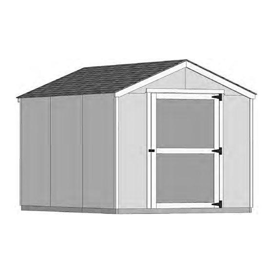
16992 01/10/2022 ASSEMBLY MANUAL A Backyard Products Company GABLE 8' x 12' (243,8 x 365,8 cm) ACTUAL FLOOR SIZE IS 96 x 140-5/8" (243,8 x 357,2 cm) KEEP THIS MANUAL FOR FUTURE REFERENCE IMPORTA NT ! READ INSTRUCTIONS THOROUGHLY PRIOR TO BEGINNING ASSEMBLY. - Page 3 TOOLS Required Optional q Phillips q Tool Belt/ q Utility Knife Screwdriver Nail Pouch q Shingle Blades q Tin Snips q Drill / Driver (for drip edge) q Caulk Gun q 3/8" Drill Bit q 1/4" Drill Bit q Chalk Line q 1/2"...
- Page 4 CONCRETE FOUNDATION If you choose to install your kit on a concrete slab refer to the diagram below. Treated Sill Plate Caulk between sill plate and concrete. Flush 3-1/2" (8,9 cm) 4" (10,2 cm) Slab must be flush at the front of the shed for door opening clearance. Any over-sized slab must have the excess at the sides or back of shed.
-
Page 5: Additional Materials
ADDITIONAL MATERIALS FOUNDATION OR FLOOR MATERIALS • This shed kit includes a wood floor system. • This shed does not include any leveling materials. • See the FLOOR LEVELING section on page 7 for recommended methods and suggested materials to properly level your foor, as this will vary depending on your specific site. -
Page 6: Parts List
PARTS IDENTIFICATION AND SIZES WOOD SIZE CONVERSION CHART Part identification is Nominal Board Size Actual Size stamped on some parts. Treated lumber is stamped: 2 x 4 ....1-1/2" x 3-1/2" (3,8 x 8,9 cm) 1 x 4 ....3/4" x 3-1/2" (1,9 x 8,9 cm) 2 x 3 ....1-1/2"... - Page 7 WALL PANELS, AND DOORS DOOR 3/8 x 48 x 72" 3/8 x 46-1/8 x 72" 3/8 x 23-7/8 x 72" (1 x 121,9 x 182,9 cm) (1 x 117,2 x 182,9 cm) (1 x 60,6 x 182,9 cm) ROOF PANELS Roof panels are 7/16"...
- Page 8 FLOOR LEVELING OPTIONS There are multiple ways to level your floor frame. Our recommended leveling method is shown below. Leveling materials are not included in this kit. PREFERRED METHOD - 4x4 TREATED RUNNERS 96" (243,8 cm) Runners are generally 12" (30,5 cm) from ends of foor fram.
-
Page 9: Parts Required
FLOOR FRAME PARTS REQUIRED: 3" (7,6 cm) TREATED 2 x 4 x 44-5/8" (5,1 x 10,2 x 113,3 cm) NOTE: TREATED Look for 2 x 4 x 48" (5,1 x 10,2 x 121,9 cm) TREATED Stamp. 2 x 4 x 92-5/8" (5,1 x 10,2 x 235,3 cm) TREATED 2 x 4 x 93"... - Page 10 LEVEL AND SQUARE FLOOR FRAME Before attaching floor decking, it is important to level and square the floor frame. A level and square floor frame is required to correctly construct your shed. BEGIN See page 7 for the preferred floor leveling method. Use level and check the frame is level before applying floor panels.
- Page 11 FLOOR PANELS PARTS REQUIRED: 2" (5,1 cm) 3/4" GAUGE BLOCK 5/8 x 44-5/8 x 96" (1,6 x 113,3 x 243,8 cm) Install all foor panels with the rough side (painted grid lines) facing up. Ensure your foor frame is square by installing one panel and squaring frame. BEGIN Place the 44-5/8 x 96"...
- Page 12 FLOOR PANELS PARTS REQUIRED: x110 2" (5,1 cm) 5/8 x 48 x 96" (1,6 x 121,9 x 243,8 cm) Install (2) 48"x 96" panels flush to installed panels. Install middle panel first. Secure panels with 2" nails spaced 6" apart on edges and 12" apart inside panels. Flush 6"...
- Page 13 IMPORTANT! Check the foor frame for level after installing foor panels. Re-level if needed. • The foor should be used as a stable work surface for wall construction. HINT: • Organize your assembly procedure during the build process to avoid over-handling of the walls. BACK WALL SIDE WALL SIDE WALL...
- Page 14 SIDE WALL FRAMES PARTS REQUIRED: 3" (7,6 cm) 2 x 3 x 46-5/16" (5,1 x 7,6 x 117,6 cm) 5/8" x 2-1/2" x 46-5/16" (1,6 x 6,3 x 117,6 cm) OSB 2" (5,1 cm) 2 x 3 x 67-3/8" (5,1 x 7,6 x 171,1 cm) 5/8"...
- Page 15 SIDE WALL PANELS PARTS REQUIRED: 2" (5,1 cm) TEMPORARY SPACER 3/4" GAUGE BLOCK 2 x 3 x 13" (5,1 x 7,6 x 33 cm) 3/8 x 48 x 72" (1 x 117,2 x 182,9 cm) Install all wall panels with the primed side facing up. Ensure your wall is square by installing one panel and squaring frame.
- Page 16 SIDE WALL PANELS PARTS REQUIRED: 2" (5,1 cm) TEMPORARY SPACER 2 x 3 x 13" (5,1 x 7,6 x 33 cm) 3/8" x 46-1/8" x 72" (1 x 117,2 x 182,9 cm) panels flush to installed panel and 1-1/2" above top plate.. Install (2) 46-1/8 x 72"...
- Page 17 BACK WALL FRAME PARTS REQUIRED: GUSSET 3" (7,6 cm) TEMPORARY SUPPORT 2 x 3 x 34" (5,1 x 7,6 x 86,4 cm) 2 x 3 x 91 " (5,1 x 7,6 x 231,1 cm) BEGIN on flat side. Use (3) gussets stacked under CI as support. Place on CI on edge on floor as shown.
- Page 18 BACK WALL FRAME PARTS REQUIRED: 3" (7,6 cm) 2 x 3 x 34" (5,1 x 7,6 x 86,4 cm) 3" (7,6 cm) GUSSET 2 x 3 x 96" (5,1 x 7,6 x 243,8 cm) TEMPORARY SUPPORT on PS on flat side. Use (3) gussets stacked under CI as support. Center on CI on edge on floor as shown.
- Page 19 BACK WALL PANELS PARTS REQUIRED: 2" (5,1 cm) 1-1/2" (3,8 cm) 3/8 x 48 x 72" (1 x 121,9 x 182,9 cm) Install all wall panels with the primed side up. BEGIN Place left panel on back frame, as shown. Secure horizontal framing with 2"...
- Page 20 BACK WALL PANELS PARTS REQUIRED: 2" (5,1 cm) 1-1/2" (3,8 cm) 3/8 x 48 x 72" (1 x 121,9 x 182,9 cm) Install right panel flush to installed panel and flush at top. Secure horizontal framing with 2" nails spaced 6" apart on edges and 12" apart inside panel. Secure vertical framing with using 1-1/2"...
- Page 21 BACK WALL BOTTOM PLATES PARTS REQUIRED: 2" (5,1 cm) 2 x 3 x 13" (5,1 x 7,6 x 33 cm) BEGIN Position RK on edge, 2-1/2" from outside edge and 1" from bottom edge of left wall panel (Fig A). Secure RK to wall panel with (3) 2"...
- Page 22 FRONT WALL FRAME PARTS REQUIRED: 3" (7,6 cm) 2 x 3 x 69-1/2" (5,1 x 7,6 x 176,5 cm) 2 x 3 x 96" (5,1 x 7,6 x 243,8 cm) BEGIN Arrange parts on edge on floor as shown. HINT: Secure with (2) 3"...
- Page 23 FRONT WALL PANELS PARTS REQUIRED: 2" (5,1 cm) 3" (7,6 cm) Temporary Brace 3/8 x 23-7/8 x 72" 69" (175,3) Door Stiffener (1 x 60,6 x 182,9 cm) Install all wall panels with the primed side up. BEGIN Place left panel on front wall frame, as shown Ensure panel has a 1"...
-
Page 24: Side Wall Installation
SIDE WALL INSTALLATION PARTS REQUIRED: 3" (7,6 cm) 2" (5,1 cm) 3" (7,6 cm) Temporary Support 69" (175,3) Door Stiffener BEGIN Center side wall on the floor. 1-1/2" Ensure 1-1/2" measurement is at the top. (3,8 cm) Install OO as a temporary brace. Secure with (2) 3"... -
Page 25: Back Wall Installation
BACK WALL INSTALLATION PARTS REQUIRED: 3" (7,6 cm) 2" (5,1 cm) 2" (5,1 cm) 1-1/2" (3,8 cm) 3" (7,6 cm) BEGIN Center back gable wall on the floor. Secure wall with (1) 2" screw into side wall stud and top plate. Secure wall to stud first. - Page 26 LEFT SIDE WALL INSTALLATION PARTS REQUIRED: 2" (5,1 cm) 3" (7,6 cm) 1-1/2" (3,8 cm) 2" (5,1 cm) 3" (7,6 cm) BEGIN Install left side wall on the floor. Ensure 1-1/2" measurement is at the top. Fit top plate over 1-1/2"...
- Page 27 FRONT WALL INSTALLATION PARTS REQUIRED: 1-1/2" (3,8 cm) 3" (7,6 cm) 3" (7,6 cm) 2" (5,1 cm) BEGIN Center front wall assembly on the floor. Secure lower edge of panel to floor frame with 2" nails spaced 6" apart. Angle nail into floor frame (Fig. A). Secure front wall to side walls with 1-1/2"...
- Page 28 FRONT WALL HEADER PARTS REQUIRED: 2" (5,1 cm) 1 x 3 x 55" (2,5 x 7,6 x 137,2 cm) GUSSET TEMPORARY SPACER BEGIN Center DS on PT on flat, flush to front wall panel. Use a gusset to maintain 3/8" overhang, as shown. Secure with 2"...
- Page 29 RAFTERS PARTS REQUIRED: x120 2" (5,1 cm) 6 x 24" (15,2 x 61 cm) Temporary Support 69” (175,3) Door Stiffener 2 x 4 x 54" (5,1 x 10,2 x 137,2 cm) BEGIN Place (2) rafter halves CM in corners of back wall. You will assemble (5) rafters. Secure gusset to rafter with 2"...
- Page 30 RAFTERS PARTS REQUIRED: 3" (7,6 cm) 2" (5,1 cm) Preassembled BEGIN Align rafters with the wall studs. Ensure the measurement between rafters, as shown. Secure with with (1) 2" screw through panel into end of rafter (Fig. A). NOTE: use (2) screws at siding seams. Secure rafters with (2) 3"...
- Page 31 BACK GABLE UNIT PARTS REQUIRED: 1-1/2" (3,8 cm) 2 x 3 x 17-1/2" (5,1 x 7,6 x 44,5 cm) Install gable panels with the primed side up. BEGIN Place BV on flat on floor. Place right gable panel centered on BV with a 1" overhang on bottom. Secure with (4) 1-1/2"...
- Page 32 BACK GABLE UNIT INSTALLATION PARTS REQUIRED: 3" (7,6 cm) 2" (5,1 cm) Preassembled BEGIN Lift and set back gable unit on back wall top plate, overlapping wall panels. Working inside, secure gable unit with (2) 3" screws into BV, angled into top plate (Fig. A). ENSURE GABLE IS CENTERED ON WALL BEFORE NAILING.
- Page 33 FRONT GABLE UNIT PARTS REQUIRED: 1-1/2" (3,8 cm) 2 x 3 x 17-1/2" (5,1 x 7,6 x 44,5 cm) Install gable panels with the primed side up. BEGIN Place BV on flat on floor as shown. Place right gable panel centered on BV with a 3/4" overhang on bottom and 1-3/4" overhang on top. Secure with (4) 2"...
- Page 34 FRONT GABLE UNIT INSTALLATION PARTS REQUIRED: 3" (7,6 cm) 2" (5,1 cm) Preassembled BEGIN Lift and set back gable unit on back wall top plate, overlapping wall panels. Working inside, secure gable unit with (2) 3" screws into BV, angled into top plate (Fig. A). ENSURE GABLE IS CENTERED ON WALL BEFORE NAILING.
- Page 35 TRIM PARTS REQUIRED: 2" (5,1 cm) 3/8 x 1-3/4 x 71" (1 x 4,4 x 180,3 cm) 3/8 x 1-3/4 x 72" (1 x 4,4 x 182,9 cm) BEGIN Install 71" trim flush under gable panel (Fig. A). Secure with (1) 2" nail. Install 72"...
- Page 36 GABLE TRIM PARTS REQUIRED: 1-1/4" (3,2 cm) 2 x 4 x 53-11/16" (5,1 x 10,2 x 136,4 cm) BEGIN Position one CL flush to front panel edge and center on right edge of groove (Fig. A). Secure trim with (10) 1-1/4" screws from inside. Position second CL flush to panel edge and flush to installed CL (Fig.
- Page 37 ROOF PANELS PARTS REQUIRED: 2" (5,1 cm) 3/4" GAUGE 48 x 96" BLOCK (121,9 x 243,8 cm) Roof panels may cause serious injury until securely fastened. Flush Install all roof panels with the rough side facing up (painted grid lines side). at peak Fig.
- Page 38 ROOF PANELS PARTS REQUIRED: 2" (5,1 cm) 47-7/8 x 48" (121,6 x 121,9 cm) Flush at peak Install (1) 47-7/8" x 48" panel flush to the installed panel and flush at the peak (Fig. B). Fig. B Secure panel with (2) 2" nails in the corners. Move to the opposite end.
- Page 39 ROOF PANELS PARTS REQUIRED: x108 2" (5 cm) 3/4" GAUGE 5-7/8" x 96" 5-7/8" x 48" BLOCK (14,9 x 243,8 cm) (14,9 x 121,9 cm) Install the 5-7/8" x 96" panel flush to upper installed panels. Use the gauge block to ensure the 3/4"...
- Page 40 DOOR TRIM PARTS REQUIRED: 2" (5,1 cm) 19/32" x 2-1/2" x 72-3/8" (1,5 x 6,3 x 183,8 cm) BEGIN Install (2) KY flush to the bottom of gable panels and aligned with stud. Secure each with (6) 2" nails evenly spaced. Flush Flush 48-1/2"...
- Page 41 DOOR PARTS REQUIRED: 2" (5,1 cm) Temporary Support 1 x 3 x 60" (2,5 x 7,6 x 152,4 cm) BEGIN Arrange parts as shown on flat surface. Center temporary part GUA over door. Secure temporary support GUA with (4) 2" screws. 2"...
- Page 42 DOOR PARTS REQUIRED: 3" (7,6 cm) 2" (5,1 cm) Temporary Support 69” (175,3) Door Stiffener BEGIN Install temporary support OO flush to bottom of door trim (Fig. A). Secure with (2) 3" screws. Mark center. Locate center of door opening and mark. Flush to bottom Fig.
-
Page 43: Door Hardware
DOOR HARDWARE PARTS REQUIRED: 1" (2,5 cm) 2-1/2" (6,4 cm) IMPORTANT! Verify 1/4" (0,6 cm) gap spacing on each side of door. Place top hinge flush to top and 1" (2,5 cm) from the outside of trim as shown. Repeat step for bottom hinge. Secure hinges with 2-1/2"... - Page 44 DOOR TRIM PARTS REQUIRED: 2" (5,1 cm) 69" (175,3) Door Stiffener 3/4" (1,9 cm) 3/8 x 1-3/4 x 69" (1 x 4,4 x 175,3 cm) Remove temporary support (Fig. A). Place OO 1" (2,5 cm) from side opposite of hinge. Center between floor and over-door header.
- Page 45 DOOR HARDWARE PARTS REQUIRED: 2-1/2" (6,4 cm) 1" (2,5 cm) 1-1/2" 1/8" (3 mm) Drill Bit (3,8 cm) x3 Sets Place middle hinge centered on door and 1" (2,5 cm) from the outside of trim. Secure hinge with 2-1/2" screws on trim and 1" screws on door. Pre-drill 1/8 x 1/2"...
- Page 46 DOOR TRIM AND HARDWARE PARTS REQUIRED: 2" (5,1 cm) 19/32" x 2-1/2" x 55" (1,5 x 6,3 x 176,5 cm) 3/4" (1,9 cm) Center the over-door trim ZB. Secure with 2" screws (Fig. A). Center over door. Fig. A Ensure nails are pounded into wall frame, behind the panel.
- Page 47 COLLAR TIES PARTS REQUIRED: 2" (5,1 cm) 1 x 3 x 60" (2,5 x 7,6 x 152,4 cm) BEGIN Install (2) collar ties GUA 2nd and 4th rafters (Fig. A). Ensure rafters are level and flush to roof panels. Fig. A Flush to roof panel 2"...
- Page 48 PAINT & CAULK - NOT INCLUDED - • Use acrylic latex caulk that is paintable. Caulk at all horizontal and vertical seams, between the trim and walls, and all around the door trim. • Use a high quality exterior acrylic latex paint. When painting your building, there are a few key areas that can be easily overlooked that must be painted: •...
- Page 49 SHINGLES - NOT INCLUDED - • Follow directions provided by manufacturer and these instructions. Familiarize yourself with a 3-Tab Shingle. Notch Notch SHINGLE NAIL PATTERN 1/2 " 1" Sealing Str (1,3 cm) 1" (2,5 cm) (2,5 cm) Half A Rain Slot Full Rain Slot NAILS NEVER DRIVE FASTENERS INTO OR ABOVE SEALING STRIPS.
- Page 50 SHINGLES continued... Beginning at front of shed, install first row of shingles with notch at 1" past roof edge or flush with drip edge. Roof Deck FRONT OF BACK OF SHED SHED 1" (2,5 cm) Flush with starter row. Notch - or - Drip Edge Flush with starter row.
- Page 51 SHINGLES continued... Continue installing rows of shingles to the peak. At the peak make sure there is a maximum of 5" or less to the rain slot, as shown below. If shingles overlap at ridge cut to peak with a utility knife. 5"...
- Page 52 SHINGLES - RIDGE CAP • You will finish off the top of the roof with a ridge cap made from shingles. BEGIN Hint: Use cut-off pieces first. Cut shingles into THREE pieces. 2" 2" (5,1 cm) (5,1 cm) 2" 2" 2"...
- Page 53 SHINGLES - RIDGE CAP continued... Continue installing ridge cap to back of roof. Make sure there is 4" between the shingle-color and edge of shingles. Trim cap off fush to shingles When you have 4" minimum of shingle color cut one piece to cap your roof. Install flush to shingles.
- Page 54 16992 8' x 12' Order Form CATEGORY PART DESCRIPTION PART SIZE PART ITEM # BUILDING QTY. PART ID Vertical Door Supports 2 X 3 X 69 1/2' Q 69080000000 Eave Wall Studs 2 X 3 X 67 3/8" Q 67060000000 Eave Wall Top Plate "A"...
- Page 55 LIMITED CONDITIONAL WARRANTY* Backyard Storage Solutions, LLC warrants the following: Every product is warranted from defects in workmanship and manufacturing for 1 year. All accessories, hardware and metal components are warranted for 2 years. All Oriented Strand Board (OSB) is warranted for 2 years Siding and Trim is warranted for 10 years.
Need help?
Do you have a question about the shedmaster GABLE 8' x 12' and is the answer not in the manual?
Questions and answers