Table of Contents
Advertisement
Quick Links
Advertisement
Table of Contents

Related Manuals for Datalogic VS-CRX


Summary of Contents for Datalogic VS-CRX
- Page 1 VS-CRX PRODUCT REFERENCE GUIDE Smart Vision Sensor...
- Page 2 Electronic versions of this document may be downloaded from the Datalogic website (www.datalogic.com). If you visit our website and would like to make comments or suggestions about this or other Datalogic pub- lications, please let us know via the "Contact" page.
-
Page 3: Table Of Contents
TABLE OF CONTENTS PREFACE ........................VI About this Manual ......................vi Manual Conventions ........................... vi Technical Support ......................vi Support Through the Website ......................vi Reseller Technical Support ....................... vii ............................. vii COMPLIANCE ......................VIII General ........................viii Power Supply ....................... viii EMC Compliance ...................... - Page 4 TABLE OF CONTENTS Internal Lighting System ....................20 Accessories ........................20 Application Examples .....................21 INSTALLATION......................22 Package Contents ......................22 Mechanical Dimensions ....................23 Mounting And Positioning Smart-VS ................25 ELECTRICAL CONNECTIONS ..................26 Power Supply .........................27 Inputs ..........................27 Trigger and external push-button connection ................. 28 Outputs ..........................28 Digital I/O diagram ..........................
- Page 5 Binary file upload and download commands ..............56 Upload command format ........................56 Upload reply format ..........................56 Download command format ......................56 Download reply format ........................57 Device Procedure control Commands ................58 Procedure control command format and return codes ..............58 List of available procedure control functions ..................58 CRTJBF (CReaTeJoBFile) ......................59 CRTBCK (CReaTeBaCKup) ......................59 ULBF (UpLoadBinaryFile) ......................59...
-
Page 6: Preface
TECHNICAL SUPPORT Support Through the Website Datalogic provides several services as well as technical support through its website. Log on to (www.datalogic.com). For quick access, from the home page click on the search icon , and type in the name of the product you’re looking for. -
Page 7: Reseller Technical Support
Reseller Technical Support An excellent source for technical assistance and information is an authorized Datalogic reseller. A reseller is acquainted with specific types of businesses, application software, and computer systems and can provide individualized assistance. PRODUCT REFERENCE GUIDE VII... -
Page 8: Compliance
Datalogic commercial reference contacts. Since April 20th, 2016 the main European directives applicable to Datalogic products require inclusion of an adequate analysis and assess- ment of the risk(s). This evaluation was carried out in relation to the applicable points of the standards listed in the Declaration of Conformity. -
Page 9: Fcc Compliance
FCC COMPLIANCE Modifications or changes to this equipment without the expressed written approval of Datalogic could void the authority to use the equipment. This device complies with PART 15 of the FCC Rules. Operation is subject to the follow- ing two conditions: (1) This device may not cause harmful interference, and (2) this device must accept any interference received, including interference which may cause undesired operation. -
Page 10: Handling
HANDLING The Smart-VS is designed to be used in an industrial environment and is built to with- stand vibration and shock when correctly installed, however it is also a precision prod- uct and therefore before and during installation it must be handled correctly to avoid damage. - Page 11 • Do not weld the device into position. It can cause electrostatic, heat or reading window damage. • Do not spray paint near the sensor. It can cause reading window damage. PRODUCT REFERENCE GUIDE XI...
-
Page 12: General View
GENERAL VIEW Figure 1 - General View 1. Bracket Mounting Holes (2) 7. Power - I/O Connector 2. Power On LED 8. Lens 3. Ethernet Connection LED 9. LED Aiming System 4. 90° Rotating Connector Block 10. Red Spot (NO GOOD) 5. - Page 13 Figure 2 - HMI Interface Details HMI CONFIGURATION NO GOOD object • in Teach phase: blinking, NO GOOD object teaching • in Run phase: NO GOOD object detected • for future use Trigger • in Teach phase: trigger input status •in Run phase: trigger received GOOD object •...
-
Page 14: Rapid Configuration
CHAPTER 1 RAPID CONFIGURATION CONNECT THE SYSTEM Figure 3 shows an example illustrating how to connect the system. In this layout the result signals are connected to the PLC while it is possible to configure and monitor the device by the Host PC. The device is activated by an External Trigger (photoelectric sensor) when the object enters its reading zone. -
Page 15: Mount And Position The Device
MOUNT AND POSITION THE DEVICE MOUNT AND POSITION THE DEVICE 1. To mount the Smart-VS, use the mounting bracket to obtain the most suitable position for the device. The most common mounting configuration is shown in the figure below. Skew Tilt Figure 4 - Positioning with Mounting Bracket PRODUCT REFERENCE GUIDE 2... - Page 16 RAPID CONFIGURATION 2. When mounting the Smart-VS take into consideration these three ideal label posi- tion angles: Pitch or Skew 10° to 20° and Tilt 0°, although the device can operate at any tilt and skew angle provided the object feature to be inspected fits into the Field Of View (FOV).
-
Page 17: Hmi Button Configuration
HMI BUTTON CONFIGURATION HMI BUTTON CONFIGURATION Button Teaching Procedure The Run LED will blink until the Teaching procedure is entered (e.g. device factory default). Long press (> 4s, until the red LED on HMI lights up) the HMI Button to enter the Teach- ing procedure. -
Page 18: Button Incremental Teaching Procedure (Optional)
RAPID CONFIGURATION 7. Short press (< 1s) the HMI Button to acquire the image. More than one NO GOOD object can be acquired. 8. Long press (> 4s, until the red LED on HMI lights up) the HMI Button to enter the auto- matic learning procedure (LEDs game). -
Page 19: Button Re-Teaching Procedure (Optional)
HMI BUTTON CONFIGURATION 3. Long press (> 4s, until the red LED on HMI lights up) the HMI Button to start acquiring NO GOOD objects. Red LED and red spot start blinking. 4. New NO GOOD object images can be added to the current job. -
Page 20: Firmware Rollback And Reset Configurations (Optional)
RAPID CONFIGURATION Firmware Rollback and Reset Configurations (optional) It is possible to perform a firmware Rollback to the second to last software version installed or a complete Reset Configurations. NOTE: It is suggested to close the Smart-VS WebApp before performing the procedures above. -
Page 21: Using The Smart-Vs Webapp
USING THE SMART-VS WEBAPP USING THE SMART-VS WEBAPP Before using a Smart-VS device, a Teaching procedure must be performed. Teaching can be completed either using the embedded HMI (see ) or the Button Teaching Procedure Smart-VS WebApp graphic user interface. NOTE: To access the Smart-VS WebApp, Google Chrome is the recom- mended Internet browser. -
Page 22: Teaching
RAPID CONFIGURATION Import Job To import one or more jobs from another device. New Job To create a new job through the Teaching wizard. Refer to " Teaching" on page 9 Settings Restore When a Settings Backup of a device has been completed (refer to " Utilities"... -
Page 23: Step 1: Image Setup
USING THE SMART-VS WEBAPP Step 1: Image Setup On the Image Setup page, select the Start Automatic Setup to automatically set the Focus Distance, the Exposure Time, and the Sensor Gain parameters (suggested). Alter- natively, select Advanced Image Settings to manually set the parameters. It is also possible to move the Field of View based on the application needs, which can be useful when objects of different batch formats must be inspected on the same line. -
Page 24: Step 3: Acquire No Good
RAPID CONFIGURATION Step 3: Acquire NO GOOD On the Acquire NO GOOD page, one or more NO GOOD objects can be acquired by clicking on the Teach button. It is recommended to acquire as many NO GOOD images as the known number of instances to be treated as NO GOOD. NOTE: The GOOD and NO GOOD boxes can store a total of 6 images, of which at least one per box. -
Page 25: Monitoring
USING THE SMART-VS WEBAPP Monitoring The Monitoring page is divided into an upper bar, a main area, and a bottom bar. The upper bar contains the job name to the left. Use the drop-down menu to switch to another job (if present). NOTE: If you want the selected job to be the running and startup job, click on the Play button before leaving the page. - Page 26 RAPID CONFIGURATION To start acquiring objects, two options are available: Save and Play with External Trigger Play with Self-Trigger Single shot The Play button is also a Save button: click on it before leaving the page to store any change. NOTE: The Play with Self-Trigger button is not an actual operating mode (output signals are not driven).
-
Page 27: Settings
USING THE SMART-VS WEBAPP Settings This page contains IP Settings and Global Settings. It can be reached using the hamburger icon on the upper right corner. The parameters under Job Settings are variable for each job, which means that any change will only be valid for the current job: Trigger Input Delay: the delay to apply prior to the acquisition process of the trig- •... -
Page 28: Utilities
RAPID CONFIGURATION Utilities The Utilities page can be reached using the hamburger icon on the upper right corner. This page is divided into three parts: • Device Information: information about the device model, serial number, software version, and GUI version. •... -
Page 29: Introduction
CHAPTER 2 INTRODUCTION PRODUCT DESCRIPTION Smart-VS is a sensor with learning ability and easy to set, suitable for any presence and orientation object detection. Smart-VS can solve all the applications where a very simple installing procedure is requested without the need of particularly smart camera features. Thanks to its algorithm technology, Smart-VS is the ideal solution for application prob- lems related to machine format adaptability and flexibility that a sensor or sensor sys- tem cannot solve as easily. -
Page 30: Excellent Performance
INTRODUCTION Excellent Performance • Electronic focus control • 50 ... 150 mm operating distance • Image Cropping for shorter acquisition time • Algorithm for fast and simple application setup Ease of Setup • Quick installation by using a user-friendly, sensor-like HMI for easy and intuitive setup •... -
Page 31: Indicator And Keypad Button
INDICATOR AND KEYPAD BUTTON INDICATOR AND KEYPAD BUTTON 3 4 5 6 7 Figure 6 - Indicators The following LED indicators are located on the device: blue LED indicates that the device is connected to the power supply (Figure 6, 1) yellow LED indicates connection to the on-board Ethernet network (Figure 6, 2) The colors and meaning of the five LEDs are illustrated in the following table:... -
Page 32: Aiming System
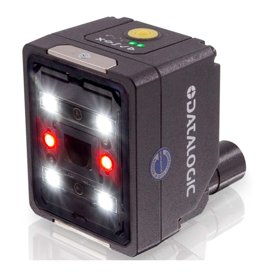
INTRODUCTION AIMING SYSTEM There are two red LED pointers that project two equidistant square patterns onto the target area. The object feature to be detected should be centered between the two squares. Aiming LED Aiming LED Figure 7 - Smart-VS Aiming LEDs LED SPOTS There are two LED spots that can be activated to project light onto the target area to indicate that a GOOD or NO GOOD object has been detected. -
Page 33: Model Selection And Order Information
MODEL SELECTION AND ORDER INFORMATION MODEL SELECTION AND ORDER INFORMATION Model Smart-VS-MR-5-150-WH-O Description SVS WP 150mm OUT Optics 7 mm Illuminator White polarized 3 OUT + 2 IN + ETH Order number CRX13237 INTERNAL LIGHTING SYSTEM The Smart-VS illuminator is composed of 4 white LEDs with polarized filter. Figure 9 - Smart-VS illuminator ACCESSORIES The following accessories can be used with Smart-VS. -
Page 34: Application Examples
INTRODUCTION APPLICATION EXAMPLES Smart-VS has been developed for different uses in the secondary packaging and auto- motive industries, food and beverage applications for bottling, cosmetic packaging, and all those markets where the following detection applications are needed: Application Solved cases (OK / NOT OK) Label presence Cap orientation Cap presence... -
Page 35: Installation
CHAPTER 3 INSTALLATION PACKAGE CONTENTS Verify that the Smart-VS device and all the parts supplied with the equipment are pres- ent and intact when opening the packaging; the list of parts includes: • Smart-VS (w/connector plug/cover) • Quick Reference Guide •... -
Page 36: Mechanical Dimensions
INSTALLATION MECHANICAL DIMENSIONS Smart-VS can be installed to operate in different positions. The two screw holes (M3 x 4mm depth) on the body of the device are for mechanical fixture. The diagrams below give the overall dimensions of the device and may be used for its installation. - Page 37 MECHANICAL DIMENSIONS Figure 12 - Overall Dimensions; Connector at 90° PRODUCT REFERENCE GUIDE 24...
-
Page 38: Mounting And Positioning Smart-Vs
INSTALLATION MOUNTING AND POSITIONING SMART-VS Using the Smart-VS mounting brackets you can obtain rotation on the various axes of the device as shown in the diagram below: Figure 13 - Positioning with Mounting Bracket 25 SMART-VS... -
Page 39: Electrical Connections
CHAPTER 4 ELECTRICAL CONNECTIONS Smart-VS can be connected through one of the available CAB-GDxx accessory cables. Figure 14 - M12 17-pin Power and I/O Connector The recommended cables 95A900052 and 95A900053 (refer to " Accessories" on page ) terminate in an M12 17-pin connector on the Smart-VS side and 9 stripped wires on the other side. -
Page 40: Power Supply
ELECTRICAL CONNECTIONS Previous Smart-VS versions use CAB-GDxx cables that terminate in an M12 17-pin con- nector on the Smart-VS side and 17 stripped wires on the other side. These wires have the following functionalities: POWER AND I/O CONNECTOR PINOUT (cables with 17 stripped wires) NAME COLOR DESCRIPTION... -
Page 41: Trigger And External Push-Button Connection
OUTPUTS These inputs are optocoupled and can be driven by both NPN and PNP type commands. NOTE: Polarity insensitive inputs assure full functionality even if pins A and B are exchanged. Trigger and external push-button connection The following table shows how to connect the Trigger and Remote inputs. RECOMMENDED CONNECTION NOTES A Normally Open push-button is... -
Page 42: Data Valid Timing Details
ELECTRICAL CONNECTIONS Overrun conditions (see " ) are signaled raising both the Troubleshooting" on page 39 GOOD and NO GOOD output signals. NOTE: Although not strictly necessary, it is recommended to connect and process all the output signals in order to have complete system informa- tion for diagnostics and troubleshooting. -
Page 43: On-Board Ethernet Interface
ON-BOARD ETHERNET INTERFACE ON-BOARD ETHERNET INTERFACE The on-board Ethernet Interface can be used for WebApp access and Telnet communi- cation. The WebApp is accessible opening an Internet browser (Google Chrome is recom- mended) and entering the device IP address 192.168.3.100 in the address bar. Telnet communication can be established by connecting to device IP at port 23. -
Page 44: Typical Layouts
CHAPTER 5 TYPICAL LAYOUTS The following typical layouts refer to system hardware configurations. Dotted lines in the figures refer to optional hardware configurations within the particular layout. NOTE: All software configurations are made through the Smart-VS WebApp, which connects to the reader through the on-board Ethernet interface. -
Page 45: Webapp For Initial Configuration And Occasional Monitoring
WEBAPP FOR INITIAL CONFIGURATION AND OCCASIONAL MONITORING WEBAPP FOR INITIAL CONFIGURATION AND OCCASIONAL MONITORING In addition to the previous setup, a PC can be connected via Ethernet for initial configu- ration and occasional monitoring. A point-to-point Ethernet connection is recommended. A presence sensor or the machine electrical phase is necessary to trigger image acquisi- tion. -
Page 46: Setup With Telnet Communication For Job Switching
TYPICAL LAYOUTS SETUP WITH TELNET COMMUNICATION FOR JOB SWITCHING If more than one Job is needed, Job switching can be done via Telnet communication. An Ethernet switch can be used to ease the connection, but a dedicated LAN is still rec- ommended, since the Smart-VS is configured with a fixed IP address. -
Page 47: Reading Features
CHAPTER 6 READING FEATURES FOV CALCULATION Use the data in the following table to calculate the FOV for your application, referring to Figure 19 and the formula below. View Angle View Angle View Angle Min Reading Horizontal Vertical Diagonal Distance 11 mm 19°... -
Page 48: Detection Diagram
READING FEATURES DETECTION DIAGRAM The following diagram shows the maximum obtainable Field of View for object inspec- tion. NOTE: All features of interest related to the object inspection should be included in the Field of View. 35 SMART-VS... -
Page 49: Multi Job Configuration
CHAPTER 7 MULTI JOB CONFIGURATION The Smart-VS can manage Multi Job operations. This feature is useful when different object batches must be inspected within a single machine. Up to 32 Jobs can be stored in the device internal memory. Job switching can be performed either via Smart-VS WebApp or Telnet communication. JOB SWITCHING VIA SMART-VS WEBAPP To recall a Job in the Smart-VS WebApp, go to the Monitoring page and select the Job ID from the Current Job list. -
Page 50: Job Switching Via Telnet Communication
MULTI JOB CONFIGURATION JOB SWITCHING VIA TELNET COMMUNICATION Jobs can also be recalled via Ethernet connection using a Telnet communication. Open a TCP/IP Telnet session using a Telnet client with the following parameters: • IP: Device IP Address (default 192.168.3.100) •... -
Page 51: Maintenance
CHAPTER 8 MAINTENANCE CLEANING Clean the lens cover periodically for continued correct operation of the device. See " General View" on page xii Dust, dirt, etc. on the lens cover may alter the device performance. Repeat the operation frequently in particularly dirty environments. Use soft material and alcohol to clean the lens cover and avoid any abrasive substances. -
Page 52: Troubleshooting
CHAPTER 9 TROUBLESHOOTING TROUBLESHOOTING GUIDE PROBLEM SUGGESTION Overrun occurrences are mostly due to a noisy trigger signal and/or a too fast sequence of trigger events (e.g. more than two events every 50 ms). Overrun Choose a proper Debounce filter time and/or adjust the line speed to have 20 pieces per second. - Page 53 TROUBLESHOOTING GUIDE PROBLEM SUGGESTION This may occur after a software update that broke compatibility with the previous version. • Keep using latest software update (delete stored jobs): access the WebApp and clear all configurations using the Clear Configurations All HMI LEDs blink on power-up button on the Utilities page.
-
Page 54: Technical Features
APPENDIX A TECHNICAL FEATURES ELECTRICAL FEATURES Power Supply Voltage 10 to 30 Vdc Consumption 0.40 - 0.14 A (4.2 W) max Communication Interfaces 10/100 Mbit/s Ethernet (embedded) Inputs Opto-coupled and polarity insensitive Max. Voltage 30 Vdc Max. Input Current 10 mA Outputs PP, NPN or PNP short circuit protected;... - Page 55 ENVIRONMENTAL FEATURES Operating Temperature -10 to 50 C (14 to 122 °F) Storage Temperature -20 to 70 C (-4 to 158 °F) Max. Humidity 90% non condensing 14 mm @ 2 to 10 Hz; 1.5 mm @ 13 to 55 Hz; Vibration Resistance EN 60068-2-6 2 g @ 70 to 500 Hz;...
-
Page 56: Tcp/Ip Communication
APPENDIX B TCP/IP COMMUNICATION CONNECTION The TCP/IP communication requires that a connection be initiated between the two devices. The Smart-VS (server) is listening on port 1023 and the PLC or PC (clients), must send a connection request to establish communication. When the communication is established, commands can be sent to the device. -
Page 57: Protocol Overview
PROTOCOL OVERVIEW PROTOCOL OVERVIEW The client sends a command to the Smart-VS and receives a reply with the result. The Smart-VS (server) is able to process only one command at a time. There are two types of commands: 1. Device control commands 2. -
Page 58: Use Of Asynchronous Features
TCP/IP COMMUNICATION Use of asynchronous features An asynchronous feature must be started with the appropriate command. It will not be possible to run multiple asynchronous features at the same time. During the execution of the asynchronous feature, the device can be queried about the status of the activity. Once the activity is terminated, it will be possible for the client to request the finaliza- tion of the task, if provided, the finalization command will also contain the reply. -
Page 59: Delimiters And Separator
PROTOCOL OVERVIEW Scenario 2 The client starts the task and immediately asks for its f i na li z at i o n . Th e r e ply w ill b e s en t at the end of the task. Smart-VS Smart-VS (Server) -
Page 60: Device Control Commands
TCP/IP COMMUNICATION DEVICE CONTROL COMMANDS These commands allow to remotely control some features of the device. They are encoded in ASCII with a defined grammar. Command format Command Parameter 1 Parameter N Figure 25: Control command frame structure • Command → encoding containing the command. •... -
Page 61: List Of Available Device Control Functions
DEVICE CONTROL COMMANDS List of available device control functions COMMAND FUNCTION PARAMETER TYPE Bank number to be CRTJB Create a new job configured, name to be asynchronous assigned to the job MDFJB Modify a job Bank number to be changed synchronous Exit the configuration EXTJB... -
Page 62: Return Codes
TCP/IP COMMUNICATION Return codes The return code is contained in all replies as a parameter following the name of the command to which the reply is related. The return code allows to understand if the command was successful or rejected. CODE NAME DESCRIPTION... -
Page 63: Crtjb (Createjob)
DEVICE CONTROL COMMANDS CRTJB (CReaTeJoB) Allows you to start a configuration session. The device switches from the “Running” state to the “Configuration” state. By sending the command, the auto-setup of the pho- tometric parameters and the focus distance is automatically done based on the object positioned in front of the device. -
Page 64: Extjb (Exitjob)
TCP/IP COMMUNICATION EXTJB (EXiTJoB) It allows to exit without saving an editing session\job creation. Syntax: EXTJB<CR><LF> Reply: EXTJB;ReturnCode<CR><LF> Possible return codes: • Success → Command successful. • NotInSession→ The command was called without a configuration session being started (the device is in running state). •... -
Page 65: Bnkst (Bankstatus)
DEVICE CONTROL COMMANDS BNKST (BaNKSTatus) It allows to check if a bank contains a job or not. The reply also contains the job name. Syntax: BNKST;BankId<CR><LF> BankId: Number of the bank to be checked. Reply: BNKST;ReturnCode;BankStatus;JobName<CR><LF> BankStatus: bank status. VALUE LABEL Empty Full... -
Page 66: Acqimg (Acquireimage)
TCP/IP COMMUNICATION ACQIMG (ACQuireIMaGe) It allows acquiring an image that will be saved among the reference images of the spec- ified class within the job being edited/created. Syntax: ACQIMG;LabelID<CR><LF> LabelID: index of the label to be assigned to the acquired image. INDEX LABEL GOOD... -
Page 67: Gtats (Getasynctaskstatus)
DEVICE CONTROL COMMANDS GTATS (GeTAsyncTaskStatus) Query the device about the status and type of asynchronous task in progress. Syntax: GTATS<CR><LF> Reply: GTATS;ReturnCode;AsyncTaskType;AsyncTaskStatus<CR><LF> AsyncTaskType: identification code of the asynchronous task. CODE ASYNCHRONOUS TASK TYPE Creating a new job Job training Creation of binary file containing a job Creation of binary file containing device backup Saving a file on the internal memory Not relevant... -
Page 68: Fnztrn (Finalizetraining)
TCP/IP COMMUNICATION FNZTRN (FiNaliZeTRaiNing) Finalize the asynchronous job training command and actually save the job in flash (“ TRNJB (TRaiNJoB)" on page 51 Syntax: FNZTRN<CR><LF> Reply: FNZTRN;ReturnCode <CR><LF> Possible return codes: • Success → Command successful. • NotInProgress → No asynchronous tasks in progress. •... -
Page 69: Binary File Upload And Download Commands
BINARY FILE UPLOAD AND DOWNLOAD COMMANDS BINARY FILE UPLOAD AND DOWNLOAD COMMANDS These commands allow to upload and download binary files from the device and check the status of the procedures. They are divided into two types of commands: 1. Upload and download. 2. -
Page 70: Download Reply Format
TCP/IP COMMUNICATION Download reply format The reply remains encoded in ASCII. Command Return Code Binary File • Command → command to which the reply is related. • Separator → standard separator of protocol (see “ Delimiters and separator" on page 46 •... -
Page 71: Device Procedure Control Commands
DEVICE PROCEDURE CONTROL COMMANDS DEVICE PROCEDURE CONTROL COMMANDS Procedure control command format and return codes The Procedure control command format is the same as the Device control command format, see “ Device control commands" on page 47 For the Return Codes see “ Return codes"... -
Page 72: Crtjbf (Createjobfile)
TCP/IP COMMUNICATION CRTJBF (CReaTeJoBFile) Allows the device to start the creation of the binary file containing the information relating to a single job. The device switches from the “Running” state to the “Configura- tion” state. Syntax: CRTJBF;BankId<CR><LF> BankId: index of the bank containing the job whose binary file is to be created. Reply: CRTJBF;Returncode<CR><LF>... -
Page 73: Dlbf (Downloadbinaryfile)
DEVICE PROCEDURE CONTROL COMMANDS DLBF (DownLoadBinaryFile) Allows you to download a binary file from the exchange area on the device. Syntax: DLBF <CR><LF> Reply: DLBF;Returncode;Binaryfile<CR><LF> BinaryFile: binary file downloaded from the exchange area. Possible return codes: • Success → command successful. •... -
Page 74: Stbck (Storebackup)
TCP/IP COMMUNICATION STBCK (SToreBaCKup) It allows to save the binary file containing the device backup on the device's flash mem- ory. The file must be previously uploaded to the exchange area. The device switches from the “Running” state to the “Configuration” state. Syntax: STBCK;Force <CR><LF>... -
Page 75: Fnzbck (Finalazebackup)
DEVICE PROCEDURE CONTROL COMMANDS FNZBCK (FiNalaZeBaCKup) Finalize the asynchronous command to create a binary file containing the device backup (“ CRTBCK (CReaTeBaCKup)" on page 59 Syntax: FNZBCK<CR><LF> Reply: FNZBCK;ReturnCode;FileSizeByte <CR><LF> FileSizeByte: Returns the size of the created file in bytes. The size of the file to be down- loaded from the device, due to the base64 encoding, can be obtained with the following formula: or divided by 3, rounded up to the nearest integer, then multiplied by 4. -
Page 76: Example Upload Of A Binary File
TCP/IP COMMUNICATION Example Upload of a binary file In order to upload a binary file to a device it is necessary to perform two steps: 1. Upload the package to your device. 2. Save the package in Flash. Scenario 1 The finalization of the saving is requested once the actual end of the task has been veri- fied. -
Page 77: Scenario 2
DEVICE PROCEDURE CONTROL COMMANDS Scenario 2 The finalization of the saving is requested without verifying the actual end of the task. Smart-VS Smart-VS (Server) (Server) Client RECEIVING FILE SAVING FILE PRODUCT REFERENCE GUIDE 64... -
Page 78: Example Downloading A Binary File
TCP/IP COMMUNICATION Example Downloading a binary file In order to download a binary file from a device it is necessary to perform two steps: 1. Request package preparation from the device. 2. Download the package. Scenario 1 The file size is requested once the package creation has been successfully completed. Smart-VS Smart-VS (Server) -
Page 79: Scenario 2
DEVICE PROCEDURE CONTROL COMMANDS Scenario 2 The finalization of the task is requested without verifying the actual end of the task. Smart-VS Smart-VS (Server) (Server) Client PREPARING FILE PREPARING BUFFER RECEIVING FILE Protocol exceptions In the case of syntax errors, two exceptions can be generated by the protocol. The format of the exceptions is the same as the format of the replies to the \upload\download control commands (see “... - Page 80 © 2020-2022 Datalogic S.p.A. and /or its affiliates • All rights reserved • Without limiting the rights under copyright, no part of this documentation may be repro- duced, stored in or introduced into a retrieval system, or transmitted in any form or by any means, or for any purpose, without the express written permission of Data- logic S.p.A.
Need help?
Do you have a question about the VS-CRX and is the answer not in the manual?
Questions and answers