Datalogic Smart-VS Product Reference Manual
Smart vision sensor
Hide thumbs
Also See for Smart-VS:
- Quick reference manual (6 pages) ,
- Product reference manual (84 pages)
Table of Contents
Advertisement
Advertisement
Table of Contents

Related Manuals for Datalogic Smart-VS


Summary of Contents for Datalogic Smart-VS
- Page 1 Smart-VS™ PRODUCT REFERENCE GUIDE Smart Vision Sensor...
- Page 2 Electronic versions of this document may be downloaded from the Datalogic website (www.datalogic.com). If you visit our website and would like to make comments or suggestions about this or other Datalogic pub- lications, please let us know via the "Contact" page.
-
Page 3: Table Of Contents
Button Teaching Procedure ........................4 Button Incremental Teaching Procedure (optional) ................5 Button Re-Teaching Procedure (optional) ..................6 System Rollback and Factory Reset (optional) ..................7 Using the Smart-VS WebApp .................... 8 Teaching ...............................8 Step 1: Image Setup ........................9 Step 2: Acquire GOOD .........................9 Step 3: Acquire NO GOOD ......................10... - Page 4 Setup with Telnet Communication for Job Switching ............31 READING FEATURES ....................32 FOV Calculation ......................32 Detection Diagram ......................33 MULTI JOB CONFIGURATION ..................34 Job Switching via Smart-VS WebApp ................34 Job Switching via Telnet Communication .................35 MAINTENANCE ......................36 Cleaning ........................36 TROUBLESHOOTING ....................37 TECHNICAL FEATURES ....................
-
Page 5: Preface
WARNING TECHNICAL SUPPORT Support Through the Website Datalogic provides several services as well as technical support through its website. Log on to ( www.datalogic.com For quick access, from the home page click on the search icon , and type in the name of the product you’re looking for. -
Page 6: Reseller Technical Support
PREFACE Reseller Technical Support An excellent source for technical assistance and information is an authorized Datalogic reseller. A reseller is acquainted with specific types of businesses, application software, and computer systems and can provide individualized assistance. VI SMART-VS... -
Page 7: Compliance
Datalogic commercial reference contacts. Since April 20th, 2016 the main European directives applicable to Datalogic products require inclusion of an adequate analysis and assess- ment of the risk(s). This evaluation was carried out in relation to the applicable points of the standards listed in the Declaration of Conformity. -
Page 8: Fcc Compliance
FCC COMPLIANCE Modifications or changes to this equipment without the expressed written approval of Datalogic could void the authority to use the equipment. This device complies with PART 15 of the FCC Rules. Operation is subject to the follow- ing two conditions: (1) This device may not cause harmful interference, and (2) this device must accept any interference received, including interference which may cause undesired operation. -
Page 9: Handling
HANDLING The Smart-VS is designed to be used in an industrial environment and is built to with- stand vibration and shock when correctly installed, however it is also a precision prod- uct and therefore before and during installation it must be handled correctly to avoid damage. - Page 10 HANDLING • Do not weld the device into position. It can cause electrostatic, heat or reading window damage. • Do not spray paint near the sensor. It can cause reading window damage. X SMART-VS...
-
Page 11: General View
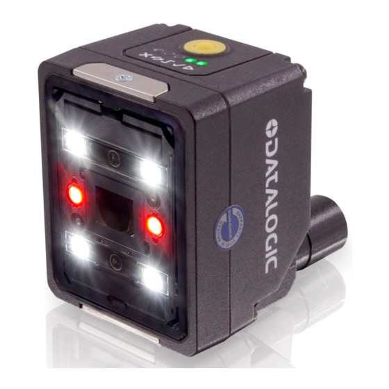
GENERAL VIEW Figure 1 - General View 1. Bracket Mounting Holes (2) 7. Power - I/O Connector 2. Power On LED 8. Lens 3. Ethernet Connection LED 9. LED Aiming System 4. 90° Rotating Connector Block 10. Red Spot (NO GOOD) 5. - Page 12 • in Teach phase: trigger input status •in Run phase: trigger received GOOD object • in Teach phase: blinking, GOOD object teaching • in Run phase: GOOD object detected • steady: device in Run phase • blinking: Teaching required XII SMART-VS...
-
Page 13: Rapid Configuration
PLC while it is possible to configure and monitor the device by the Host PC. The device is activated by an External Trigger (photoelectric sensor) when the object enters its reading zone. Figure 3 - Smart-VS layout example PRODUCT REFERENCE GUIDE 1... -
Page 14: Mount And Position The Device
RAPID CONFIGURATION MOUNT AND POSITION THE DEVICE 1. To mount the Smart-VS, use the mounting bracket to obtain the most suitable position for the device. The most common mounting configuration is shown in the figure below. Skew Tilt Figure 4 - Positioning with Mounting Bracket... - Page 15 MOUNT AND POSITION THE DEVICE 2. When mounting the Smart-VS take into consideration these three ideal label posi- tion angles: Pitch or Skew 10° to 20° and Tilt 0°, although the device can operate at any tilt and skew angle provided the object feature to be inspected fits into the Field Of View (FOV).
-
Page 16: Hmi Button Configuration
5. Long press (> 4s, until the red LED on HMI lights up) the HMI Button to start acquiring NO GOOD objects. The red LED and the red spot start blinking. 6. Place the NO GOOD object in front of the Aiming System. Check the Trigger LED. 4 SMART-VS... -
Page 17: Button Incremental Teaching Procedure (Optional)
HMI BUTTON CONFIGURATION 7. Short press (< 1s) the HMI Button to acquire the image. More than one NO GOOD object can be acquired. 8. Long press (> 4s, until the red LED on HMI lights up) the HMI Button to enter the auto- matic learning procedure (LEDs game). -
Page 18: Button Re-Teaching Procedure (Optional)
If errors occur and the new Teaching is not finalized, the current job will not be over- written. In case of mistakes, the procedure can be aborted before entering the learning procedure by pressing the HMI Button for approx. 2 seconds until the HMI yellow LED turns on. NOTE 6 SMART-VS... -
Page 19: System Rollback And Factory Reset (Optional)
3 seconds, then release and press it again during the LED blinking sequence. All saved jobs are erased with a Factory Reset. It is suggested to close the Smart-VS WebApp before performing the pro- cedures above. Connect to or refresh the WebApp to check the device soft- ware version (see "... -
Page 20: Using The Smart-Vs Webapp
Device information and the software update feature are available on the page. Utilities Teaching To perform Teaching on the Smart-VS device, enter a job name, select the bank where to store it, click on the Create Job button, and follow the procedure described below. 8 SMART-VS... -
Page 21: Step 1: Image Setup
USING THE SMART-VS WEBAPP Step 1: Image Setup On the Image Setup page, select the Start Automatic Setup to automatically set the Focus Distance, the Exposure Time, and the Sensor Gain parameters (suggested). Alter- natively, select Advanced Image Settings to manually set the parameters. -
Page 22: Step 3: Acquire No Good
A maximum of 6 images can be stored in both GOOD and NO GOOD boxes. NOTE Click on an acquired object in the NO GOOD box and select DELETE to delete NOTE After adding at least one NO GOOD object, you can click on the Teach button. 10 SMART-VS... -
Page 23: Step 4: Learn
USING THE SMART-VS WEBAPP Step 4: Learn This step is completed automatically. Once the device is trained, the graphic user interface switches to the Monitoring page. Monitoring The Monitoring page is divided into an upper bar, a main area, and a bottom bar. - Page 24 After clicking on one of the Play icons, the newly added acquisitions will be used by the device in addition to those stored during the initial Teaching procedure. Furthermore, the Smart-VS WebApp allows image saving. Any image shown in the WebApp can be saved clicking on it and selecting Save.
-
Page 25: Settings
USING THE SMART-VS WEBAPP It is recommended to enable the browser option “Ask where to save each file before downloading”. NOTE The following options are also available: Show all images or just one category between GOOD, NO GOOD, and OVERRUN... -
Page 26: Utilities
The Utilities page can be reached using the hamburger icon on the upper right corner. This page contains: • Device information: information about the device model, serial number, software versions, and GUI version. • Operations: to upgrade the device software clicking on the Upload Package but- ton. 14 SMART-VS... -
Page 27: Introduction
CHAPTER 2 INTRODUCTION PRODUCT DESCRIPTION Smart-VS is a sensor with learning ability and easy to set, suitable for any presence and orientation object detection. Smart-VS can solve all the applications where a very simple installing procedure is requested without the need of particularly smart camera features. -
Page 28: Excellent Performance
PP, NPN or PNP short-circuit protected outputs Industrial Strength • Industrial compact visual sensor • Rugged metal construction • Sealed circular M12 connectors • IP65 and IP67 protection class • 50 °C max operating temperature • Supply voltage ranges from 10 to 30 Vdc 16 SMART-VS... -
Page 29: Indicator And Keypad Button
INDICATOR AND KEYPAD BUTTON INDICATOR AND KEYPAD BUTTON 3 4 5 6 7 Figure 6 - Indicators The following LED indicators are located on the device: blue LED indicates that the device is connected to the power supply (Figure 6, 1) yellow LED indicates connection to the on-board Ethernet network (Figure 6, 2) The colors and meaning of the five LEDs are illustrated in the following table:... -
Page 30: Aiming System
There are two LED spots that can be activated to project light onto the target area to indicate that a GOOD or NO GOOD object has been detected. Green Spot Red Spot Figure 8 - Smart-VS Good / No Good LED Spots 18 SMART-VS... -
Page 31: Model Selection And Order Information
3 OUT + 2 IN + ETH Order number 959971320 INTERNAL LIGHTING SYSTEM The Smart-VS illuminator is composed of 4 white LEDs with polarized filter. Figure 9 - Smart-VS illuminator ACCESSORIES The following accessories can be used with Smart-VS. Accessory Order No. -
Page 32: Application Examples
INTRODUCTION APPLICATION EXAMPLES Smart-VS has been developed for different uses in the secondary packaging and auto- motive industries, food and beverage applications for bottling, cosmetic packaging, and all those markets where the following detection applications are needed: Application Solved cases (OK / NOT OK) -
Page 33: Installation
CHAPTER 3 INSTALLATION PACKAGE CONTENTS Verify that the Smart-VS device and all the parts supplied with the equipment are pres- ent and intact when opening the packaging; the list of parts includes: • Smart-VS (w/connector plug/cover) • Quick Reference Guide •... -
Page 34: Mechanical Dimensions
INSTALLATION MECHANICAL DIMENSIONS Smart-VS can be installed to operate in different positions. The two screw holes (M3 x 4mm depth) on the body of the device are for mechanical fixture. The diagrams below give the overall dimensions of the device and may be used for its installation. - Page 35 MECHANICAL DIMENSIONS Figure 12 - Overall Dimensions; Connector at 90° PRODUCT REFERENCE GUIDE 23...
-
Page 36: Mounting And Positioning Smart-Vs
INSTALLATION MOUNTING AND POSITIONING SMART-VS Using the Smart-VS mounting brackets you can obtain rotation on the various axes of the device as shown in the diagram below: Figure 13 - Positioning with Mounting Bracket 24 SMART-VS... -
Page 37: Electrical Connections
ELECTRICAL CONNECTIONS Smart-VS can be connected through one of the available CAB-GDxx accessory cables. These terminate in an M12 17-pin connector on the Smart-VS side and 17 free leads on the other side. CAB-GDxx wires have the following functionalities: Figure 14 - M12 17-pin Power, COM, and I/O Connector... -
Page 38: Power Supply
An anti-disturbance filter, by default, is implemented in software on both inputs. The value can be changed through the software parameter Debounce Filter. See " Settings" or refer to the Settings section of the Smart-VS WebApp User’s Guide for fur- on page 13 ther details on these parameters. -
Page 39: Outputs
Image acquisition starts on the Leading edge of the input trigger signal (default, can be changed to Trailing edge via Smart-VS WebApp). A Debounce time can be set on the Smart-VS WebApp to reject noisy trigger signals. Each trigger event corresponds to a Data Valid signal indicating that the Output signals can be sampled. -
Page 40: On-Board Ethernet Interface
Figure 15 - M12 8-pin Standard Ethernet Network Connector STANDARD ETHERNET NETWORK CONNECTOR PINOUT NAME DESCRIPTION Transmit data (positive pin) Transmit data (negative pin) Receive data (positive pin) Receive data (negative pin) Not connected Not connected Not connected Not connected 28 SMART-VS... -
Page 41: Typical Layouts
Ethernet interface. NOTE SENSOR-LIKE SETUP The Smart-VS is connected directly to the machine control system. An optional push-button is recommended if Teaching is frequently performed for prod- uct batch changes or if the device is not easily accessible. -
Page 42: Webapp For Initial Configuration And Occasional Monitoring
In addition to the previous setup, a PC can be connected via Ethernet for initial configu- ration and occasional monitoring. A point-to-point Ethernet connection is recommended. A presence sensor or the machine electrical phase is necessary to trigger image acquisi- tion. Figure 17 - WebApp Setup 30 SMART-VS... -
Page 43: Setup With Telnet Communication For Job Switching
An Ethernet switch can be used to ease the connection, but a dedicated LAN is still rec- ommended, since the Smart-VS is configured with a fixed IP address. A presence sensor or the machine electrical phase is necessary to trigger image acquisi- tion. -
Page 44: Reading Features
Figure 19 - Reading Distance References Example The FOV at a reading distance of 100 mm is: = 2 [(100 mm + 11 mm) * tan (19°/2)] 37 mm = 2 [(100 mm + 11 mm) * tan (14.5°/2)] 28 mm 32 SMART-VS... -
Page 45: Detection Diagram
DETECTION DIAGRAM DETECTION DIAGRAM The following diagram shows the maximum obtainable Field of View for object inspec- tion. All features of interest related to the object inspection should be included in the Field of View. NOTE PRODUCT REFERENCE GUIDE 33... -
Page 46: Multi Job Configuration
Job switching can be performed either via Smart-VS WebApp or Telnet communication. JOB SWITCHING VIA SMART-VS WEBAPP To recall a Job in the Smart-VS WebApp, go to the Monitoring page and select the Job ID from the Current Job list. -
Page 47: Job Switching Via Telnet Communication
JOB SWITCHING VIA TELNET COMMUNICATION JOB SWITCHING VIA TELNET COMMUNICATION Jobs can also be recalled via Ethernet connection using a Telnet communication. Open a TCP/IP Telnet session using a Telnet client with the following parameters: • IP: 192.168.3.100 • Port: 23 The following commands are available to switch Jobs and retrieve information on the running Job: COMMAND... -
Page 48: Maintenance
General View" on page xi Dust, dirt, etc. on the lens cover may alter the device performance. Repeat the operation frequently in particularly dirty environments. Use soft material and alcohol to clean the lens cover and avoid any abrasive substances. 36 SMART-VS... -
Page 49: Troubleshooting
• Check that the GOOD object and NO GOOD object LEDs light up cor- rectly. The PLC does not receive GOOD or NO • If the PLC requires a PNP signal, check that the Smart-VS outputs GOOD signals from the Smart-VS sensor are set as Push-Pull or PNP. -
Page 50: Technical Features
50 ms from input trigger a. The embedded Ethernet interface is intended for configuration only through connection to the device IP address 192.168.3.100. Point-to-Point connection is recommended. OPTICAL FEATURES Operating Distance 50 - 150 mm View Angle 19° 38 SMART-VS... - Page 51 PHYSICAL FEATURES H x W x L Dimensions Smart-VS with connector at 0° 78 x 47 x 38 mm (3.1 x 1.9 x 1.5 in) Smart-VS with connector at 90° 58 x 47 x 58 mm (2.3 x 1.9 x 2.3 in) Weight 173 g (6.1 oz)
- Page 52 © 2020 Datalogic S.p.A. and /or its affiliates • All rights reserved • Without limiting the rights under copyright, no part of this documentation may be reproduced, stored in or introduced into a retrieval system, or transmitted in any form or by any means, or for any purpose, without the express written permission of Datalogic S.p.A.
Need help?
Do you have a question about the Smart-VS and is the answer not in the manual?
Questions and answers