Table of Contents
Advertisement
Quick Links
TL46 IO-Link
Instruction Manual
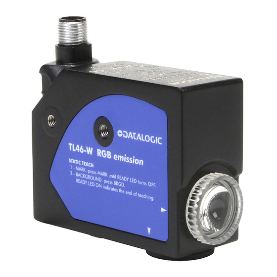
CONTROLS ( W model )
OUTPUT LED (yellow)
The yellow LED indicates the output status.
READY LED (green)
The steady green LED ON indicates normal functioning. If
quickly flashing, it indicates an output overload.
MARK PUSH-BUTTON
Pressing the MARK push-button activates the mark acquisition.
BKGD PUSH-BUTTON
Pressing the BKGD push-button activates the background
acquisition.
Refer to "Settings (W model)" for the correct procedures during the setting phase.
CONTROLS ( WH model )
OUTPUT LED (yellow)
The yellow LED indicates the output status.
DISPLAY (4 green digits)
In MARK mode the display indicates a value relative to the
light quantity diffused by the target, in COLOR mode it shows
the text "COLr". The display turns off after 10s of keyboard
inactivity.
READY LED (green)
The steady green LED ON indicates normal functioning. If
quickly flashing, it indicates an output overload.
DELAY LED
The green DELAY LED ON indicates the timing activation on the digital output.
KEYLOCK LED
The green KEYLOCK LED ON indicates that the keylock is active.
,
,
PUSH-BUTTONS
Please refer to "Settings" for the correct use procedures during the setting or acquisition
phases.
DIMENSIONS
Datalogic S.r.l.
Via S. Vitalino 13 - 40012 Calderara di Reno - Italy
Tel: +39 051 3147011 - Fax: +39 051 3147205 - www.datalogic.com
Helpful links at www.datalogic.com: Contact Us, Terms and Conditions, Support.
For information about the disposal of Waste Electrical and Electronic Equipment (WEEE),
please refer to the website at www.datalogic.com.
© 2020 Datalogic S.p.A. and/or its affiliates - ALL RIGHTS RESERVED. - Without limiting the rights under copyright, no part
of this documentation may be reproduced, stored in or introduced into a retrieval system, or transmitted in any form or by
any means, or for any purpose, without the express written permission of Datalogic S.p.A. and/or its affiliates. Datalogic and
the Datalogic logo are registered trademarks of Datalogic S.p.A. in many countries, including the U.S.A. and the E.U. All
other trademarks and brands are property of their respective owners. Datalogic reserves the right to make modifications and
improvements without prior notification.
821006511 Rev. B
INSTALLATION
The sensor can be positioned by means of the two Ø3.5mm housing holes or using threaded
M5 holes with 6mm max. depth.
Warning: the use of excessively long screws can damage the product.
The connector can be oriented at five different positions by rotating the block. The position
chosen is guaranteed by a mechanical blocking system.
The rotation can be carried out even after sensor installation as the connector block is
completely self-contained inside the housing.
The operating distance is measured starting from the lens front face.
The reading direction can be changed inverting the cap and lens.
Mark detection on a reflective surface is improved adjusting the
beam direction to 5° ... 20° from surface axis.
CONNECTIONS
TECHNICAL DATA
Power Supply
Ripple
Current consumption
(output current
excluded)
Output
Output current
Output saturation
voltage
Response time
Switching frequency
Delay
No delay in factory configuration (programmable through IO-Link)
LIGHT/DARK selection
Selectable through wire or IO-Link in Dynamic acquisition
Indicators
Push-buttons
Operating temperature
Storage temperature
Operating distance
Depth of field
Min. spot dimension
Emission type
Ambient light rejection
Dielectric strength
1500 VAC, 1 min between electronics and housing
Insulating resistance
> 20 MΩ, 500 VDC between electronics and housing
Vibrations
Shock resistance
11 ms (30 G) 6 shocks for each axis (EN60068-2-27)
Housing material
Lens material
Mechanical protection
Connections
Weight
AtEx 2014/34/EU
W model
12 ... 30 Vcc (limit values)
2 Vpp max.
<30 mA max. @ 24 Vcc (display off)
2 outputs type PNP or Push-Pull (selectable);
30 Vcc max. (short-circuit protection)
(Push-Pull factory configuration)
100 mA max. (total of both outputs)
≤ 2 V
20 μs
25 kHz
Automatic in Mark/Background acquisition;
OUTPUT LED (yellow) / READY LED (green)
MARK, BACKGROUND
-10 ... 55 °C
-20 ... 70 °C
9 mm
± 3 mm
0.8 x 4 mm
2
blue (465nm) / green (520nm) / red (630nm)
with automatic selection
according to EN 60947-5-2
0.5 mm amplitude, 10...55 Hz frequency,
for each axis (EN60068-2-6)
Aluminum
PMMA
IP67
M12 5-pole connector
170 g. max
II 3G EX nA II T6 ;
II 3D EX tD A22 IP67 T85°C
Advertisement
Table of Contents

Subscribe to Our Youtube Channel
Related Manuals for Datalogic IO-Link TL46


Summary of Contents for Datalogic IO-Link TL46
- Page 1 PMMA Mechanical protection IP67 © 2020 Datalogic S.p.A. and/or its affiliates - ALL RIGHTS RESERVED. - Without limiting the rights under copyright, no part Connections M12 5-pole connector of this documentation may be reproduced, stored in or introduced into a retrieval system, or transmitted in any form or by any means, or for any purpose, without the express written permission of Datalogic S.p.A.
-
Page 2: Tolerance Setting
If the acquisition has been successful, the sensor returns to normal operation. If it has failed WH model due to insufficient contrast, the “FAIL” text blinks on the display (WH model) / the READY Power Supply 12 ... 30 Vcc (limit values) LED blinks quickly (W model). -
Page 3: Hysteresis Setting
SETTINGS in both modes (WH model) MARK/COLOR SETTING The sensor can be configured in MARK or COLOR mode. Select “MArk” or “COLr” in the parameter menu to switch the mode. HYSTERESIS SETTING The sensor hysteresis level can be adjusted. The “HYSt” text appears on the display by pressing the push-button. - Page 4 ACCESSORY FUNCTIONS (all models) ON/OFF DISPLAY SETTING Turn off the display during normal operation to save power consumption. Setting the OFF mode, the display turns off when the sensor is normally functioning. It turns REMOTE INPUT on for 10s after a keyboard command. Select “dSOn” or “dSOF” in the parameter menu to set The REMOTE signal can perform the acquisition functions without using the SET push- the display ON or OFF.
-
Page 5: Physical Layer
Length Value/Range Description Data Type Access* Remark (dec) Name (offset) 0x0010 (16) Vendor Name 9 octets DATALOGIC Informative StringT 0x0011 (17) Vendor Text 19 octets Empower your vision StringT 0x0012 (18) Product Name 14 octets See “Device variant collection” Detailed product name... - Page 6 Observation / Diagnostic Parameters Index Subindex Data Parameter Object Name Length Value/Range Description Access* Remark (dec) (offset) Type Device 0x0028 (40) Process Data Input 2 octets Read last valid Process Data Input from PDin channel specific 0x0045 (69) Sampled Analog Signal value RED 2 octets 0...4095 Value of analog signal with RED emission (COLOR mode, WH model only)
- Page 7 Teach-in Parameters Index Parameter Object Subindex Length Value/Range Description Data Type Access* Remark (dec) Name (offset) C/Q and DO outputs are antivalent. Teach SSC1 0x003A (58) TI Select 1 octet 0x00 = SSC1 (default, C/Q pin and DO pin) Selection for Teach-in channel (volatile) UIntegerT equals to teach SSC2 Teach-in State...
- Page 8 Device Specific Parameters Index (dec) Parameter Object Name Length Subindex (offset) Value/Range Description Data Type Access* Remark 0 = no delay (default) Saved in non-volatile memory. 0x1 = Delay OFF ENABLED UIntegerT 1 octet 1(64) Select Delay mode Max. Value 15000 ms 0x2 = Delay ON ENABLED UIntegerT (OFF/ON/OFF-ON)
-
Page 9: Process Data
Events Event code (dec) Event name Event mode Event type Device status Remarks 0x4220 (16928) Temperature underrun Appears / Disappears Warning Out of specification 0x4210 (16912) Temperature overrun Appears / Disappears Warning Out of specification 0x5100 (20736) General power supply fault Appears / Disappears Error Failure... - Page 11 Timestamp Index (dec) Parameter Object Name Length Subindex (offset) Value/Range Description Data Type Access* Remark 1 octet 1(32) EVENT_1 (ID=0x01): Switch Counter Threshold Reached 1 octet 2(24) EVENT_2 (ID=0x02): Temperature underrun (Event mode APPEARS) 0x00: disabled (default) Event that generates a 0x00B8 (184) Timestamp Trigger 1 octet...
- Page 12 The Job function allows saving the configuration and retrieving it later. Parameter Subindex Data Index (dec) Length Value/Range Description Access* Remark Object Name (offset) Type 1..20 (WH) Load the job corresponding to the selected number Saved in non-volatile 0x0066 (102) Load Job 1 octet UIntegerT...
- Page 13 IP67 连接 M12 5-针连接器 重量 最大 170 g. © 2020 Datalogic S.p.A. 和/或其附属机构 - 保留所有权利。- 在不限制版权所有权,或未经 Datalogic S.p.A. 和/或其 II 3G EX nA II T6; 附属机构的书面许可的情况下,不得对此文档的任何一部分进行复制、存储或将其引入检索系统,不得以任何形式、通过任何 AtEx 2014/34/EU 方法对此文档进行传播,不得将此文档用于任何目的。Datalogic 和 Datalogic 标志是 Datalogic S.p.A. 在美国和欧盟等 II 3D EX tD A22 IP67 T85°C 诸多国家或地区的注册商标。所有其他商标和品牌均是其相关所有者的财产。Datalogic...
- Page 14 如果采集成功,传感器返回正常工作状态。如果因对比度不足导致失败,显示面板闪 WH 型号 烁“FAIL”文本(WH 型号)/READY LED 快速闪烁(W 型号)。按下 SET 按钮(WH 型号)/ 电源 12 ...30 Vcc(极限值) MARK 按钮(W 型号),传感器返回到之前的设置。 纹波 最大 2 Vpp 从头开始重复该步骤。 电流消耗(不含输出 24 Vcc 下最大不超过 30 mA(显示面板关闭) 电流) 2 种输出类型,PNP 或推挽式(可选); 输出 最大 30 Vcc(短路保护) (PP 出厂配置) 输出电流 最大...
- Page 15 两种模式下的设定(WH 型号) MARK/COLOR 设置 可在 MARK 或 COLOR 模式下配置传感器。 在参数菜单中选择“MArk”或“COLr”以切换模式。 迟滞设定 传感器迟滞水平可进行调节。 按下 后,显示器上显示“HYSt”文本。 按下 SET 可以切换先前设置的模式。 常开/闭设置(仅在 COLOR 模式下) 释放按钮时,先前设置的值将闪烁。 COLOR 模式下的输出可以配置为常开或常闭。 在参数菜单中选择“OPEn”或“CLOS”以切换输出。 高迟滞 按下 SET 切换到先前设置的模式。 中迟滞 延迟开启设置 DELAY 是参考标记进入检测区域后的输出延迟激活。延迟避免了对快速发生事件的检 低迟滞 测。例如,阴影颜色(亮-暗-亮)的标记可以被检测到两次。 检测到 通过按下 或 来进行水平切换。 目标 按下 SET 按钮保存新的迟滞值。 未检测到...
- Page 16 开/关显示面板设置 辅助功能(所有型号) 在正常运行期间,请关闭显示面板以节省功耗。 设置 OFF 模式,当传感器正常工作时,显示面板关闭。输入键盘命令后,显示面板将开启 10 REMOTE 输入 秒钟。在参数菜单中选择“dSOn”或“dSOF”以将显示面板设置为 ON 或 OFF。 REMOTE 信号无需使用 SET 按钮即可执行采集功能。通过 IO-Link 选择引脚 2 或 5。 REMOTE 线连接到 +Vcc 等同于按下 SET 按钮。如果连接到 GND 或未连接,则等同于未 按下 SET 按钮。 按下 SET 切换到先前设置的显示模式。 REMOTE SET 按钮 未按下 +Vcc 按下...
- Page 17 标识参数 索引 子索引 参数对象名称 长度 值/范围 说明 数据类型 访问* 备注 (十进制) (偏移) 0x0010 (16) 供应商名称 9 个八位字节 DATALOGIC 信息性 StringT 0x0011 (17) 供应商文本 19 个八位字节 强化您的视野 StringT 0x0012 (18) 产品名称 14 个八位字节 请参见 “时间戳表格” 详细产品名称 StringT 0x0013 (19) 产品 ID 5 个八位字节...
- Page 18 观察/诊断参数 索引 子索引 参数对象名称 长度 值/范围 说明 数据类型 访问* 备注 (十进制) (偏移) 0x0028 (40) 处理数据输入 2 个八位字节 从 PDin 通道读取上一有效处理数据输入 设备指定 0x0045 (69) 红色采样模拟信号值 2 个八位字节 0...4095 红色发射模拟信号值(COLOR 模式,仅限 WH 型号) UIntegerT 0x0046 (70) 绿色采样模拟信号值 2 个八位字节 0...4095 绿色发射模拟信号值(COLOR 模式,仅限 WH 型号) UIntegerT 0x0047 (71) 蓝色采样模拟信号值...
- Page 19 示教参数 索引 子索引 参数对象名称 长度 值/范围 说明 数据类型 访问* 备注 (十进制) (偏移) C/Q 和 DO 输出非等价。教学 SSC1 和教学 SSC2 0x003A (58) TI 选择 1 个八位字节 0x00 = SSC1(默认,C/Q 引脚和 DO 引脚) 示教通道选择(易失) UIntegerT 相等 示教状态 1(0) UIntegerT4 0x003B (59) TI 结果 1 个八位字节...
- Page 20 设备指定参数 索引(十进制) 参数对象名称 长度 子索引(偏差) 值/范围 说明 数据类型 访问* 备注 0 = 无延迟(默认) 保存在非易失性存储中。 0x1 = 延迟关闭已启用 UIntegerT 1 个八位字节 1(64) 选择延迟模式 最大值 15000 ms UIntegerT 0x2 = 延迟开启已启用 (关闭/开启/关闭-开启) UIntegerT 0x3 = 延迟开启+关闭已启用 0x0048 (72) 延迟设置 设置“无延迟”后,延迟开启和关闭 值都将重置为零。先设置延迟类型, 4 个八位字节 2(32) 0 ..15000 延迟开启值...
- Page 21 事件 时间代码(十进制) 事件名称 事件模式 事件类型 设备状态 备注 0x4220 (16928) 温度不足 出现/消失 报警 超出规格 0x4210 (16912) 温度过高 出现/消失 报警 超出规格 0x5100 (20736) 总电源故障 出现/消失 错误 失败 0x8CAA (36010) 短路 - 检查安装 出现/消失 错误 失败 0x8CA0 (36000) 振动超限 出现/消失 报警 超出规格 0x8CA1 (36001) 检测到冲击...
- Page 22 向下计数 计数器模式 - 自动 计数器模式 - 静态 输出切换 输出切换 (上升或下 (上升或下 降沿) 降沿) 时间 时间 重置计 数器 切换计数 器值 时间 阈值计数器 阈值计数器-1 切换计数 器值 阈值计数器 时间 时间 切换计数器已到达 切换计数器已到达 阈值 阈值 时间 时间 如果切换频率高于 MinCycleTime,则计数器超出位 (处理数据)将在 2 个周期后复位 向上计数 计数器模式 - 静态 计数器模式...
- Page 23 时间戳 索引(十进制) 参数对象名称 长度 子索引(偏差) 值/范围 说明 数据类型 访问* 备注 1 个八位字节 1(32) EVENT_1 (ID=0x01): 切换计数器已到达阈值 1 个八位字节 2(24) EVENT_2 (ID=0x02): 温度不足(事件模式出现) 0x00:已禁用(默认) 0x00B8 (184) 时间戳触发 1 个八位字节 3(16) EVENT_3 (ID=0x03): 温度过高(事件模式出现) UIntegerT 生成时间戳的事件 0x01:已启用 1 个八位字节 4(8) EVENT_4 (ID=0x04): 短路 1 个八位字节...
- Page 24 作业功能允许保存配置并在以后检索。 作业 索引(十进制) 参数对象名称 长度 子索引(偏差) 值/范围 说明 数据类型 访问* 备注 1..20 (WH) 加载与所选编号对应的作业 0x0066 (102) 加载作业 1 个八位字节 UIntegerT 保存在非易失性存储中 1..10 (W) 1..10 在标记模式下选择 10 种配置,11...20 在颜色模式下选择 10 种配置 1..20 (WH) 选择下一保存操作的作业编号 0x0067 (103) 选择作业编号 1 个八位字节 UIntegerT 保存在非易失性存储中 1..10 (W) 1..10 在标记模式下选择...
-
Page 25: Garanzia
Prodotti dopo la vendita. Il Periodo di Garanzia Beispiel aber nicht nur Brände, Wasserschäden, Überschwemmungen, ; (10) tout consommable ou équivalent (par exemple, des câbles, les sarà di tre anni dalla data di spedizione da parte di Datalogic, se non sonstige Naturkatastrophen,... - Page 26 CE Compliance CE marking states the compliance of the product with essential requirements listed in the applicable European directive. Since the directives and applicable standards are subject to continuous updates, and since the manufacturer promptly adopts these updates, therefore the EU declaration of conformity is a living document. The EU declaration of conformity is available for competent authorities and customers through the manufacturer’s commercial reference contacts. Since April 20th, 2016 the main European directives applicable to the products require inclusion of an adequate analysis and assessment of the risk(s).
-
Page 27: Installation
© 2012 - 2017 Datalogic S.p.A. and/or its affiliates ALL RIGHTS RESERVED. Without limiting the rights under copyright, no part of this documentation may be reproduced, stored in or introduced into a retrieval system, or transmitted in any form or by any means, or for any purpose, without the express written permission of Datalogic S.p.A. - Page 28 © 2007 - 2017 Datalogic S.p.A. and/or its affiliates ALL RIGHTS RESERVED. Without limiting the rights under copyright, no part of this documentation may be reproduced, stored in or introduced into a...
- Page 29 PARAMETER SETTING SETTING IN MARK MODE SETTING IN COLOR MODE Some parameters can be changed entering the menu: MARK/COLOR mode, DETECTION (MARK-BACKGROUND) COLOR DETECTION NORMALLY OPEN/CLOSE, DELAY ON, DELAY OFF, display orientation and powering - Position mark in front of the sensor light spot and press the push-button until the Position the color in front of the sensor light spot and press the push-button until the...
-
Page 30: Accessory Functions
In the LIGHT mode, the output is active with light marks on dark backgrounds. disposal at the end of its life. Datalogic recommends disposing of the product in compliance with Setting the OFF mode when the sensor is normally functioning, the display turns In the DARK mode, the output is active with dark marks on light backgrounds. - Page 31 PARAMETER SETTING SETTING IN MARK MODE SETTING IN COLOR MODE Some parameters can be changed entering the menu: MARK/COLOR mode, DETECTION (MARK-BACKGROUND) COLOR DETECTION NORMALLY OPEN/CLOSE, DELAY ON, DELAY OFF, display orientation and powering - Position mark in front of the sensor light spot and press the push-button until the Position the color in front of the sensor light spot and press the push-button until the...
- Page 32 In the LIGHT mode, the output is active with light marks on dark backgrounds. disposal at the end of its life. Datalogic recommends disposing of the product in compliance with Setting the OFF mode when the sensor is normally functioning, the display turns In the DARK mode, the output is active with dark marks on light backgrounds.
Need help?
Do you have a question about the IO-Link TL46 and is the answer not in the manual?
Questions and answers