Table of Contents
Advertisement
Available languages
Available languages
Quick Links
S8 IO-Link
Instruction Manual
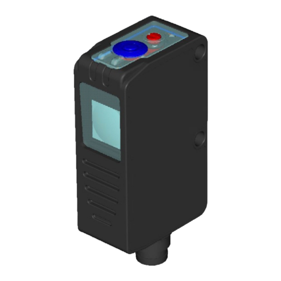
CONTROLS
OUTPUT LED (yellow)
The yellow LED indicates the output status.
READY LED (green)
The green LED ON indicates normal functioning.
SET PUSH-BUTTON
The acquisition procedure is activated by pressing the SET push-button. The control obtained
with the SET push-button can be made externally with the REMOTE input. Set Pin 2 as
REMOTE through IO-Link.
DELAY TRIMMER (W03)
The digital output's delay is selected/deselected by a monoturn trimmer.
LIGHT/DARK TRIMMER (T53, B53, U03)
The light/dark mode is selected by a monoturn trimmer.
Please refer to "Settings" for the correct use procedures.
CAUTION: the max. mechanical rotation range of the trimmer
is 240°. Do not force over of the maximum and minimum
positions.
INSTALLATION
The sensor can be positioned by means of the two housing
holes using two screws (M3X18 or longer, 0.8Nm max.
tightening torque) with washers.
Various orientable fixing brackets to ease the sensor positioning
are available (please refer to the accessories listed in the
general catalogue).
The operating distance is measured from the front surface
of the sensor optics.
Mark detection on a reflective surface is improved adjusting
the beam direction to 5° ... 20° from surface axis.
CONNECTIONS
Datalogic S.r.l.
Via S. Vitalino 13 - 40012 Calderara di Reno - Italy
Tel: +39 051 3147011 - Fax: +39 051 3147205 - www.datalogic.com
Helpful links at www.datalogic.com: Contact Us, Terms and Conditions, Support.
For information about the disposal of Waste Electrical and Electronic Equipment (WEEE),
please refer to the website at www.datalogic.com.
© 2020 Datalogic S.p.A. and/or its affiliates - ALL RIGHTS RESERVED. - Without limiting the rights under copyright, no part of this
documentation may be reproduced, stored in or introduced into a retrieval system, or transmitted in any form or by any means, or
for any purpose, without the express written permission of Datalogic S.p.A. and/or its affiliates. Datalogic and the Datalogic logo are
registered trademarks of Datalogic S.p.A. in many countries, including the U.S.A. and the E.U. All other trademarks and brands are
property of their respective owners. Datalogic reserves the right to make modifications and improvements without prior notification.
821007030 Rev. A
TECHNICAL DATA
Power Supply
12 ... 30 VDC (Class 2 UL508) (reverse polarity protected)
Ripple
2 Vpp max.
Current consumption
(output current
40 mA max.
excluded)
Output / Alarm output
PNP or NPN N.O.; 30 VDC max. (short-circuit protection)
(S8T only)
Pull-down/up resistance = 47 KΩ
Output current
100 mA max. (overload protection)
Output saturation
≤ 2 V
voltage
50 μs (W03, B53)
Response time
250 μs (T53)
250 μs / 1 ms (U03)
10 kHz (W03, B53)
Switching frequency
2 kHz (T53)
500 Hz / 2 kHz (U03)
blue (465nm) / green (520nm) / red (630nm) with automatic selection (W03)
UV LED (375nm) (U03)
red LED (λ = 645...665nm): Class1 EN 60825-1, Class II CDRH 21 CFR
Emission type
PART 1040.10
Pulsed emission: max. power ≤ 1 mW; pulse duration = 4.4 μs; frequency =
40KHz (B53)
Spot dimension
3x1 mm
(W03) / Ø 2 mm at 15 mm (U03)
2
9 mm (W03), 10...30 mm (U03)
Operating distance
2 m (EG2) on R2 reflector (T53)
(typical values)
0...10 m on R2 reflector (B53)
Depth of field (W03)
± 2 mm
LIGHT/DARK selection
Automatic (W03) / Monoturn trimmer (B53, T53, U03)
Delay selection
DELAY monoturn trimmer (W03)
Indicators
OUTPUT LED (yellow) / READY LED (green)
Operating temperature
-10 ... 55 °C
Storage temperature
-20 ... 70 °C
Dielectric strength
1500 VAC 1 min. between electronics and housing
Insulating resistance
>20 MΩ 500 VDC between electronics and housing
Ambient light rejection
according to EN 60947-5-2
Vibrations
0.5 mm amplitude, 10...55 Hz frequency, for each axis (EN60068-2-6)
Shock resistance
11 ms (30 G) 6 shocks for each axis (EN60068-2-27)
Housing material
ABS
Lens material
Window in PMMA; lens in PC
Mechanical protection
IP67
Connections
M8 4-pole connector
Weight
12 g. max
DIMENSIONS
SETTINGS
W03 Models
FINE ACQUISITION
Mark detection
The Light/Dark mode is automatically selected by the sensor.
Place the mark in front of the sensor spot and press the SET
button until the READY LED turns off or send the IO-Link Standard
command "SP1 Teach TP1".
The sensor functions alternating red, green and blue emissions.
Do not move the mark during this phase.
Background detection
Place the background in front of the sensor spot and press the SET
button again or send the IO-Link Standard command "SP1 Teach
TP2".
The sensor functions alternating red, green and blue emissions.
Do not move the background during this phase.
If the READY LED turns permanently ON the acquisition was successful. If the READY LED
blinks quickly the acquisition failed due to insufficient contrast. Press the SET button and the
sensor returns to the previous setting. Repeat procedure from the beginning. Teach-in status
can be read on IO-Link parameter "TI Result".
DYNAMIC ACQUISITION
Use dynamic acquisition to acquire moving marks. The sensor
detects the contrast between the mark and the moving background,
and automatically sets the threshold value. Place the sensor spot
in front of the target to be detected. Press the SET button until the
READY LED lights up again (3 s) or send the IO-Link Standard
command "Teach Dynamic". To end the acquisition press the SET
button or send the IO-Link Standard command "Teach Dynamic End".
The sensor functions alternating red, green and blue emissions.
LIGHT/DARK SWITCHING ( W03 )
Pressing the SET button for 5 s inverts the Light/Dark mode. Alternatively, the "SSC1/SSC2
Config" IO-Link parameters can be used.
PNP SETTING
Press the SET button for 10 s to reset Pin 4 in PNP mode. Use this feature if Pin 4 is set in
NPN mode and the sensor must be connected again to an IO-Link master.
DELAY SETTING
Delay activation
Rotate the trimmer counterclockwise.
Delay deactivation
Rotate the trimmer clockwise.
When the trimmer is enabled, the IO-Link Standard parameter "Delay Settings" can be used
for delay configuration.
U03 Models
EASY TOUCH ACQUISITION
Place the mark in front of the sensor spot and press the SET button until the READY LED
turns off. If the READY LED turns permanently ON the acquisition was successful. If the
READY LED blinks quickly the acquisition failed due to insufficient contrast.
Press the SET button and the sensor returns to the previous setting. Alternatively, use the IO-
Link Standard command "SP1 Single Value Teach" for Easy Touch Acquisition.
If the Easy Touch acquisition fails due to insufficient contrast, try again using the Mark-
Background Acquisition described below.
MARK - BACKGROUND ACQUISITION
Mark Acquisition
Place the mark in front of the sensor spot and press the SET button until the READY LED
turns back on (3 s).
Background Acquisition
Place the background in front of the sensor spot and press the SET button again. If the
READY LED turns permanently ON the acquisition was successful. If the READY LED blinks
quickly the acquisition failed due to insufficient contrast. Press the SET button and the sensor
returns to the previous setting.
Alternatively, use IO-Link Standard command "SP1 Teach TP1" for Mark Acquisition and "SP1
Teach TP2" for Background Acquisition.
MAX. SENSITIVITY SETTING
To set the maximum sensitivity, press the SET button for 5 s until the READY LED turns off
again. Alternatively, use the IO-Link Standard command "Max. Sensitivity".
PNP SETTING
Press the button for 10 s to reset Pin 4 in PNP mode.
B53 / T53 Models
SENSITIVITY SETTING
Sensitivity allignment and setting:
• Place the sensor and the reflector on opposite sides at the desired distance and aligned.
Set the maximum sensitivity for easier alignment.
• Move the sensor vertically and horizontally to determine the powering on and powering off
points of the OUTPUT LED and fix the sensor in the middle of these two points.
• Press the SET button until the READY LED turns off. The sensor acquires the reflector.
Alternatively, use the IO-Link Standard command "SP1 Single Value Teach". If the READY
LED turns permanently ON the acquisition was successful. If the READY LED blinks
quickly the acquisition failed due to insufficient contrast. Press the SET button and the
sensor returns to the previous setting. Repeat the procedure after checking the alignment
of the sensor with the reflector and the operating distance.
Check:
• Enter the detection area laterally with the object and check that the OUTPUT LED turns
on (in Dark mode).
• Remove the object and check that the OUTPUT LED turns off immediately (in Dark mode).
MAX. SENSITIVITY SETTING
To set the maximum sensitivity, press the SET button until the READY LED turn on again (3
s) or use the IO-Link Standard command "Max. Sensitivity".
PNP SETTING
Press the SET button for 10 s to reset Pin 4 in PNP mode. Use this feature if Pin 4 is set in
NPN mode and the sensor must be connected again to an IO-Link master.
SWITCHING THRESHOLD AUTOMATIC ADJUSTMENT ( T53 )
The sensor automatically adjusts the switching threshold. In case of dirty optics or reflector
the received signal decreases, after 1 minute of low signal the sensor automatically adjusts
the switching threshold to compensate for such variation avoiding a continuous cleaning of
the optics. If the received signal is too low to be adjusted by the sensor, the output remains
swtiched on and the optical parts must be cleaned.
LIGHT/DARK MODE SETTING ( B53, T53, U03 )
Light mode setting
Rotate the trimmer counterclockwise
to set the Light mode (sensor ON
with the reflector).
Dark mode setting
Rotate the trimmer clockwise to
set the Dark mode (sensor ON in
presence of an object).
Alternatively, the IO-Link Standard commands "SSC1/SSC2 Config" can be used.
OTHER FUNCTIONS
REMOTE input
The REMOTE signal carries out acquisition functions without using the SET push-button. The
REMOTE wire connected to +Vdc is equal to pressing the SET push-button, connected to
GND or not connected is equal to not pressing the SET push-button.
DO Pin (Pin 2) can be configured as REMOTE input using Output Type IO-Link parameter.
Advertisement
Table of Contents

Related Manuals for Datalogic IO-Link S8


Summary of Contents for Datalogic IO-Link S8
- Page 1 Alternatively, use the IO-Link Standard command “Max. Sensitivity”. © 2020 Datalogic S.p.A. and/or its affiliates - ALL RIGHTS RESERVED. - Without limiting the rights under copyright, no part of this documentation may be reproduced, stored in or introduced into a retrieval system, or transmitted in any form or by any means, or for any purpose, without the express written permission of Datalogic S.p.A.
-
Page 2: Installazione
Datalogic S.p.A. e/o delle sue consociate. Datalogic e il logo Datalogic sono marchi registrati di Datalogic S.p.A. depositati in diversi paesi, tra cui U.S.A. e UE. Tutti gli altri marchi registrati IMPOSTAZIONE PNP e brand sono di proprietà... -
Page 3: Installation
LED READY wieder erlischt. Alternativ dazu den IO-Link Standardbefehl „Max. Sensitivity“ urheberrechtlich geschützten Rechte einzuschränken, darf kein Teil dieser Dokumentation ohne ausdrückliche schriftliche Zustimmung der Datalogic S.p.A. und/oder ihrer Tochtergesellschaften in irgendeiner Form oder mit einem beliebigen Mittel oder verwenden. - Page 4 être reproduite, stockée ou introduite dans un système de recherche, ni transmise sous quelque forme ou par quelque moyen que ce soit, ni à quelque fin que ce soit, sans l'autorisation écrite expresse de Datalogic S.p.A. et/ou ses filiales.
- Page 5 有关处置报废电子电气设备 (WEEE) 的信息,请参阅网站 www.datalogic.com。 最高灵敏度设置 要设置最大灵敏度,请按下 SET 按钮 5 秒钟,直到 READY LED 再次熄灭。或者,使用 IO- Link 标准命令“最大灵敏度”(Max. Sensitivity)。 © 2020 Datalogic S.p.A. 和/或其附属机构 - 保留所有权利。- 在不限制版权所有权,或未经 Datalogic S.p.A. 和/或其附属机构的 书面许可的情况下,不得对此文档的任何一部分进行复制、存储或将其引入检索系统,不得以任何形式、通过任何方法对此文档进 行传播,不得将此文档用于任何目的。Datalogic 和 Datalogic 标志是 Datalogic S.p.A. 在美国和欧盟等诸多国家或地区的注册商 标。所有其他商标和品牌均是其相关所有者的财产。Datalogic 有权对本文档进行修正和改进,而无需事先通知。 PNP 设定...
-
Page 6: Physical Layer
Subindex Lenght Value/Range Description Data Type Access* Remark (dec) Name (offset) 0x0010 (16) Vendor Name 9 octets DATALOGIC Informative StringT 0x0011 (17) Vendor Text 19 octets Empower your vision StringT 0x0012 (18) Product Name 14 octets Detailed product name StringT See “Device variant collection”... - Page 7 Observation / Diagnostic Parameters Index Parameter Subindex Lenght Value/Range Description Data Type Access* Remark (dec) Object Name (offset) Process Data Device 0x0028 (40) 1 octet Read last valid Process Data Input from PDin channel Input specific 0x0041 (65) Analog Signal 2 octets Read analog signal UIntegerT...
- Page 8 Device Specific Parameters Index Parameter Subindex Lenght Value/Range Description Data Type Access* Remark (dec) Object Name (offset) 0 = no DELAY (default U03, T53, B53) 0x1 = Delay ON/OFF 1 octet 1(8) 0x2 = Delay ON Select Delay mode (OFF) UIntegerT Saved in non-volatile memory.
-
Page 9: Process Data
PROCESS DATA Process Data Input Byte 0 COUNTER EXCEED Not used ALARM (B53) TEACH-IN SSC2 (DO pin) SSC1 (C/Q pin) THRESHOLDS DEVICE VARIANT COLLECTION Product name Product ID Product text S8-PR-5-W03-0Z 00004 Contrast sensor S8-PR-5-T53-0Z 00005 Reflex transparent S8-PR-5-B53-OZ 00006 Reflex polarized laser S8-PR-5-U03-OZ 00007... - Page 10 821007030 Rev.A...
- Page 11 标识参数 索引 子索引 参数对象名称 长度 值/范围 说明 数据类型 访问* 备注 (十进制) (偏移) 0x0010 (16) 供应商名称 9 个八位字节 DATALOGIC 信息性 StringT 0x0011 (17) 供应商文本 19 个八位字节 强化您的视野 StringT 0x0012 (18) 产品名称 14 个八位字节 请参见 “Device variant collection” 详细产品名称 StringT 0x0013 (19) 产品...
- Page 12 观察/诊断参数 索引 子索引 参数对象名称 长度 值/范围 说明 数据类型 访问* 备注 (十进制) (偏移) 0x0028 (40) 处理数据输入 1 个八位字节 从 PDin 通道读取上一有效处理数据输入 设备指定 0x0041 (65) 模拟信号 2 个八位字节 读取模拟信号 UIntegerT 设备实际温度 2 个八位字节 1(64) IntegerT 2 个八位字节 2(48) 上电后设备最低温度 IntegerT 3(32) 0x0052 (82) 设备温度...
- Page 13 设备指定参数 索引 子索引 参数对象名称 长度 值/范围 说明 数据类型 访问* 备注 (十进制) (偏移) 0 = 无延迟(默认 U03,T53,B53) 0x1 = 延迟开/关 1 个八位字节 1(8) 选择延迟模式 (OFF) UIntegerT 0x2 = 延迟开启 保存在非易失性存储中。 0x4 = 延迟关闭(默认 W03) 0x0048 (72) 延迟设置 最大值 255 ms 0...(2^8)-1 1 个八位字节...
- Page 14 处理数据 处理数据输入 字节 0 未使用 警报 (B53) 计数器超过阈值 示教 SSC2(DO 引脚) SSC1(C/Q 引脚) 设备版本收集 产品名称 产品 ID 产品文本 S8-PR-5-W03-0Z 00004 对比度传感器 S8-PR-5-T53-0Z 00005 反射透明 S8-PR-5-B53-OZ 00006 反射偏振激光 S8-PR-5-U03-OZ 00007 发光传感器 扩展参数 切换计数器 索引 子索引 参数对象名称 长度 值/范围 说明 数据类型 访问* 备注...
- Page 15 向上计数 计数器模式 – 自动 计数器模式 - 静态 输出切换 输出切换 (上升或下降沿) (上升或下降沿) 时间 时间 重置计数器 切换计数器值 时间 阈值计数器 切换计数器值 阈值计数器 时间 时间 计数器超出位 计数器超出位 (处理数据) (处理数据) 时间 时间 如果切换频率高于 MinCycleTime,则计数 器超出位(处理数据) 将在 2 个周期后复位 向下计数 计数器模式 – 自动 计数器模式 - 静态 输出切换...
-
Page 16: Warranty
Datalogic, se non diversamente concordato per iscritto da beträgt drei Jahre ab dem Datum des Versands durch de la date d’expédition par Datalogic, sauf accord contraire Datalogic will not be liable under the warranty if the Product Datalogic. Datalogic, wenn von Datalogic keine andere schriftliche écrit de Datalogic. - Page 17 CE Compliance CE marking states the compliance of the product with essential requirements listed in the applicable European directive. Since the directives and applicable standards are subject to continuous updates, and since the manufacturer promptly adopts these updates, therefore the EU declaration of conformity is a living document. The EU declaration of conformity is available for competent authorities and customers through the manufacturer’s commercial reference contacts.
Need help?
Do you have a question about the IO-Link S8 and is the answer not in the manual?
Questions and answers