Datalogic Smart-VS Product Reference Manual
Smart vision sensor
Hide thumbs
Also See for Smart-VS:
- Product reference manual (52 pages) ,
- Quick reference manual (6 pages)
Table of Contents
Advertisement
Quick Links
Advertisement
Table of Contents

Related Manuals for Datalogic Smart-VS


Summary of Contents for Datalogic Smart-VS
- Page 1 Smart-VS™ PRODUCT REFERENCE GUIDE Smart Vision Sensor...
- Page 2 Trademarks Datasensing and the Datasensing logo are trademarks of Datasensing S.r.l. Datalogic and the Datalogic logo are registered trademarks of Datalogic S.p.A. in many countries, including the U.S. and the E.U. Patents www.patents.datasensing.com...
-
Page 3: Table Of Contents
Button Teaching Procedure ........................3 Button Incremental Teaching Procedure (optional) ................4 Button Re-Teaching Procedure (optional) ..................5 Firmware Rollback and Reset Configurations (optional) ..............6 Using the Smart-VS WebApp .................... 7 Dashboard Page ....................... 8 Current Bank ............................9 IP Settings ............................9 Settings Backup ..........................9 Device Information ..........................10... - Page 4 Setup with Telnet Communication for Job Switching ............35 READING FEATURES ....................36 FOV Calculation ......................36 Detection Diagram ......................37 MULTI JOB CONFIGURATION ..................38 Job Switching via Smart-VS WebApp ................38 Job Switching via Telnet Communication .................39 MAINTENANCE ......................40 Cleaning ........................40 TROUBLESHOOTING ....................41 TECHNICAL FEATURES ....................
- Page 5 GTRJB (GeTRunningJoB) ......................54 GTDVCS (GeTDeViCeStatus) .....................54 ACQIMG (ACQuireIMaGe) ......................55 CLRBNK (CLeaRBaNK) ......................55 CLRJBS (CLeaRJoBS) .......................55 GTATS (GeTAsyncTaskStatus) ....................56 FNZJB (FiNaliZeJoB) ........................56 FNZTRN (FiNaliZeTRaiNing) .....................57 Example of creating a new job ......................57 Example of incremental training ......................57 Binary file upload and download commands ..............58 Upload command format ........................58 Upload reply format ..........................58 Download command format ......................58...
-
Page 6: Preface
For quick access, from the home page click on the search icon , and type in the name of the product you’re looking for. This allows you access to download Data Sheets, Manu- als, Software & Utilities, and Drawings. VI SMART-VS... -
Page 7: Warranty
WARRANTY WARRANTY Datasensing warrants that the Products shall be free from defects in materials and workmanship under normal and proper use during the Warranty Period. Products are sold on the basis of specifications applicable at the time of manufacture and Datasensing has no obligation to modify or update Products once sold. -
Page 8: Compliance
Select the link from the downloads section of the product page. Warning This is a Class A product. In a domestic environment this product may cause radio inter- ference in which case the user may be required to take adequate measures. VIII SMART-VS... -
Page 9: Fcc Compliance
FCC Compliance Modifications or changes to this equipment without the expressed written approval of Datalogic could void the authority to use the equipment. This device complies with PART 15 of the FCC Rules. Operation is subject to the follow- ing two conditions: (1) This device may not cause harmful interference, and (2) this device must accept any interference received, including interference which may cause undesired operation. -
Page 10: Handling
HANDLING The Smart-VS is designed to be used in an industrial environment and is built to with- stand vibration and shock when correctly installed, however it is also a precision prod- uct and therefore before and during installation it must be handled correctly to avoid damage. - Page 11 • Do not weld the device into position. It can cause electrostatic, heat or reading window damage. • Do not spray paint near the sensor. It can cause reading window damage. PRODUCT REFERENCE GUIDE XI...
-
Page 12: General View
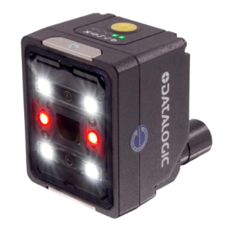
2. Power On LED 8. Lens 3. Ethernet Connection LED 9. LED Aiming System 4. 90° Rotating Connector Block 10. Red Spot (NO GOOD) 5. HMI Interface 11. Green Spot (GOOD) 6. Ethernet Connector 12. White Polarized Illuminators XII SMART-VS... - Page 13 Figure 2 - HMI Interface Details HMI CONFIGURATION NO GOOD object • in Teach phase: blinking, NO GOOD object teaching • in Run phase: NO GOOD object detected • for future use Trigger • in Teach phase: trigger input status •in Run phase: trigger received GOOD object •...
-
Page 14: Rapid Configuration
PLC while it is possible to configure and monitor the device by the Host PC. The device is activated by an External Trigger (photoelectric sensor) when the object enters its reading zone. Figure 3 - Smart-VS layout example 1 SMART-VS... -
Page 15: Mount And Position The Device
MOUNT AND POSITION THE DEVICE MOUNT AND POSITION THE DEVICE 1. To mount the Smart-VS, use the mounting bracket to obtain the most suitable position for the device. The most common mounting configuration is shown in the figure below. Skew... -
Page 16: Hmi Button Configuration
5. Long press (> 4s, until the red LED on HMI lights up) the HMI Button to start acquiring NO GOOD objects. The red LED and the red spot start blinking. 6. Place the NO GOOD object in front of the Aiming System. Check the Trigger LED. 3 SMART-VS... -
Page 17: Button Incremental Teaching Procedure (Optional)
HMI BUTTON CONFIGURATION 7. Short press (< 1s) the HMI Button to acquire the image. More than one NO GOOD object can be acquired. 8. Long press (> 4s, until the red LED on HMI lights up) the HMI Button to enter the auto- matic learning procedure (LEDs pattern). -
Page 18: Button Re-Teaching Procedure (Optional)
If errors occur and the new Teaching is not finalized, the current job will not be over- written. NOTE: In case of mistakes, the procedure can be aborted before entering the learning procedure by pressing the HMI Button for approx. 2 seconds until the HMI yellow LED turns on. 5 SMART-VS... -
Page 19: Firmware Rollback And Reset Configurations (Optional)
It is possible to perform a firmware Rollback to the second to last software version installed or a complete Reset Configurations. NOTE: It is suggested to close the Smart-VS WebApp before performing the procedures above. Connect to or refresh the WebApp to check the device software version (see "... -
Page 20: Using The Smart-Vs Webapp
To access the Smart-VS WebApp, connect to the device IP address (factory default: 192.168.3.100) via Ethernet. For systems that support the Link-Local Multicast Name Resolution (LLMNR) protocol, you can connect to the Smart-VS by typing smart-vs/ in the address bar (if there is only one device on the network) or smart-vs-[Serial Number]/ (e.g. -
Page 21: Dashboard Page
DASHBOARD PAGE DASHBOARD PAGE When connecting a new device, the “Smart-VS Dashboard” page is displayed showing: AREA DESCRIPTION Current Bank (see "Current Bank" on page IP Settings (see "IP Settings" on page Settings Backup (see "Settings Backup" on page Device Information (see "Device Information"... -
Page 22: Current Bank
Current Bank Allows to change the bank in use. Import Job To import a job previously downloaded on PC from another Smart-VS. New Job To create a new job through the Teaching wizard. Refer to " Teaching" on page 11 Monitor Allows to go to the monitoring page if the selected bank is configured. -
Page 23: Device Information
Refer to " I/O Settings" on page 17 Hamburger icon AREA DESCRIPTION Dashboard Opens the Dashboard page Monitor Opens the Monitor page I/O Settings Opens the I/O Settings page Help Opens the Smart-VS WebApp User’s guide PRODUCT REFERENCE GUIDE 10... -
Page 24: Teaching
RAPID CONFIGURATION TEACHING To perform Teaching on your Smart-VS device, enter a job name, select the bank where to store it, click on the Create Job button, and follow the procedure described below. Step 1: Image Setup On the Image Setup page, select Start Automatic Setup to automatically set the Focus Distance, the Exposure Time, and the Sensor Gain parameters (suggested). -
Page 25: Step 2: Acquire Good
TEACHING Step 2: Acquire GOOD On the Acquire GOOD page, one or more GOOD objects can be acquired by clicking on the Teach button. It is recommended to acquire as many GOOD images as the known number of instances to be treated as GOOD. NOTE: The GOOD and NO GOOD boxes can store a total of 6 images, of which at least one per box. -
Page 26: Step 3: Acquire No Good
After adding at least one NO GOOD object, you can click on the Teach button. Step 4: Learn This step is completed automatically. If it takes too long, you can stop the procedure clicking on the Stop training button. Once the device is trained, the Smart-VS WebApp switches to the Monitoring page. 13 SMART-VS... -
Page 27: Monitoring
MONITORING MONITORING The Monitoring page is divided into an upper bar, a main area, and a bottom bar. AREA DESCRIPTION Upper bar (see "Upper Bar" on page Main area (see "Main area" on page Bottom bar (see "Bottom bar" on page Upper Bar The upper bar contains the job name to the left. -
Page 28: Main Area
1. Overrun occurrences are mostly due to a noisy trigger signal and/or a too fast sequence of trigger events (e.g. more than two events every 50 ms). Choose a proper Debounce filter time and/or adjust the line speed to have 20 pieces per second. 15 SMART-VS... -
Page 29: Download The Filmstrip
MONITORING Furthermore, the Smart-VS WebApp allows image saving. Any image shown in the WebApp can be saved clicking on it and selecting Save. NOTE: It is recommended to enable the browser option “Ask where to save each file before downloading”. -
Page 30: I/O Settings
Remote Teach Input Event: available selections are Leading and Trailing. • Remote Teach Input Debounce: filter debounce time measured in μs. • • Aiming System: available selections are Always ON, Always OFF, Calibration Only. • Green/Red Spots: available selections are Calibration Only, Enabled, Disabled. 17 SMART-VS... -
Page 31: Introduction
CHAPTER 2 INTRODUCTION PRODUCT DESCRIPTION Smart-VS is a sensor with learning ability and easy to set, suitable for any presence and orientation object detection. Smart-VS can solve all the applications where a very simple installing procedure is requested without the need of particularly smart camera features. -
Page 32: Excellent Performance
PP, NPN or PNP short-circuit protected outputs Industrial Strength • Industrial compact visual sensor • Rugged metal construction • Sealed circular M12 connectors • IP65 and IP67 protection class • 50 °C max operating temperature • Supply voltage ranges from 10 to 30 Vdc 19 SMART-VS... -
Page 33: Indicator And Keypad Button
INDICATOR AND KEYPAD BUTTON INDICATOR AND KEYPAD BUTTON 3 4 5 6 7 Figure 6 - Indicators The following LED indicators are located on the device: blue LED indicates that the device is connected to the power supply (Figure 6, 1) yellow LED indicates connection to the on-board Ethernet network (Figure 6, 2) The colors and meaning of the five LEDs are illustrated in the following table:... -
Page 34: Aiming System
There are two LED spots that can be activated to project light onto the target area to indicate that a GOOD or NO GOOD object has been detected. Green Spot Red Spot Figure 8 - Smart-VS Good / No Good LED Spots 21 SMART-VS... -
Page 35: Model Selection And Order Information
3 OUT + 2 IN + ETH Order number 959971320 INTERNAL LIGHTING SYSTEM The Smart-VS illuminator is composed of 4 white LEDs with polarized filter. Figure 9 - Smart-VS illuminator ACCESSORIES The following accessories can be used with Smart-VS. Accessory Order No. -
Page 36: Application Examples
INTRODUCTION APPLICATION EXAMPLES Smart-VS has been developed for different uses in the secondary packaging and auto- motive industries, food and beverage applications for bottling, cosmetic packaging, and all those markets where the following detection applications are needed: Application Solved cases (OK / NOT OK) -
Page 37: Installation
CHAPTER 3 INSTALLATION PACKAGE CONTENTS Verify that the Smart-VS device and all the parts supplied with the equipment are pres- ent and intact when opening the packaging; the list of parts includes: • Smart-VS (w/connector plug/cover) • Quick Reference Guide •... -
Page 38: Mechanical Dimensions
INSTALLATION MECHANICAL DIMENSIONS Smart-VS can be installed to operate in different positions. The two screw holes (M3 x 4mm depth) on the body of the device are for mechanical fixture. The diagrams below give the overall dimensions of the device and may be used for its installation. - Page 39 MECHANICAL DIMENSIONS Figure 12 - Overall Dimensions; Connector at 90° PRODUCT REFERENCE GUIDE 26...
-
Page 40: Mounting And Positioning Smart-Vs
INSTALLATION MOUNTING AND POSITIONING SMART-VS Using the Smart-VS mounting brackets you can obtain rotation on the various axes of the device as shown in the diagram below: Figure 13 - Positioning with Mounting Bracket 27 SMART-VS... -
Page 41: Electrical Connections
The recommended cables 95A900052 and 95A900053 (refer to " Accessories" on page ) terminate in an M12 17-pin connector on the Smart-VS side and 9 stripped wires on the other side. These wires have the following functionalities: POWER AND I/O CONNECTOR PINOUT... -
Page 42: Power Supply
ELECTRICAL CONNECTIONS Previous Smart-VS versions use CAB-GDxx cables that terminate in an M12 17-pin con- nector on the Smart-VS side and 17 stripped wires on the other side. These wires have the following functionalities: POWER AND I/O CONNECTOR PINOUT (cables with 17 stripped wires) -
Page 43: Trigger And External Push-Button Connection
Image acquisition starts on the Leading edge of the input trigger signal (default, can be changed to Trailing edge via Smart-VS WebApp). A Debounce time can be set on the Smart-VS WebApp to reject noisy trigger signals. Each trigger event corresponds to a Data Valid signal indicating that the Output signals can be sampled. -
Page 44: Data Valid Timing Details
Data Valid timing details The Data Valid signal is raised 1 ms after the GOOD or NO GOOD signal is raised. It is lowered 1 ms before the GOOD or NO GOOD signal is lowered. *default, adjustable via Smart-VS WebApp 31 SMART-VS... -
Page 45: On-Board Ethernet Interface
ON-BOARD ETHERNET INTERFACE ON-BOARD ETHERNET INTERFACE The on-board Ethernet Interface can be used for WebApp access and Telnet communi- cation. The WebApp is accessible opening an Internet browser (Google Chrome is recom- mended) and entering the device IP address 192.168.3.100 in the address bar. Telnet communication can be established by connecting to device IP at port 23. -
Page 46: Typical Layouts
WebApp, which connects to the reader through the on-board Ethernet interface. SENSOR-LIKE SETUP The Smart-VS is connected directly to the machine control system. An optional push-button is recommended if Teaching is frequently performed for prod- uct batch changes or if the device is not easily accessible. -
Page 47: Webapp For Initial Configuration And Occasional Monitoring
WEBAPP FOR INITIAL CONFIGURATION AND OCCASIONAL MONITORING WEBAPP FOR INITIAL CONFIGURATION AND OCCASIONAL MONITORING In addition to the previous setup, a PC can be connected via Ethernet for initial configu- ration and occasional monitoring. A point-to-point Ethernet connection is recommended. A presence sensor or the machine electrical phase is necessary to trigger image acquisi- tion. -
Page 48: Setup With Telnet Communication For Job Switching
An Ethernet switch can be used to ease the connection, but a dedicated LAN is still rec- ommended, since the Smart-VS is configured with a fixed IP address. A presence sensor or the machine electrical phase is necessary to trigger image acquisi- tion. -
Page 49: Reading Features
CHAPTER 6 READING FEATURES FOV CALCULATION Use the data in the following table to calculate the FOV for your application, referring to Figure 19 and the formula below. View Angle View Angle View Angle Min Reading Horizontal Vertical Diagonal Distance 11 mm 19°... -
Page 50: Detection Diagram
READING FEATURES DETECTION DIAGRAM The following diagram shows the maximum obtainable Field of View for object inspec- tion. NOTE: All features of interest related to the object inspection should be included in the Field of View. 37 SMART-VS... -
Page 51: Multi Job Configuration
Job switching can be performed either via Smart-VS WebApp or Telnet communication. JOB SWITCHING VIA SMART-VS WEBAPP To recall a Job in the Smart-VS WebApp, go to the Monitoring page and select the Job ID from the Current Job list. -
Page 52: Job Switching Via Telnet Communication
All commands must end with #CR (carriage return, byte dec value = 13) NOTE: If the command string is sent through a pre-allocated array larger than the string itself, the unused portion of the array must be initialized to ØØ (bytes) i.e. the [NULL] character. 39 SMART-VS... -
Page 53: Maintenance
CHAPTER 8 MAINTENANCE CLEANING Clean the lens cover periodically for continued correct operation of the device. See " General View" on page xii Dust, dirt, etc. on the lens cover may alter the device performance. Repeat the operation frequently in particularly dirty environments. Use soft material and alcohol to clean the lens cover and avoid any abrasive substances. -
Page 54: Troubleshooting
• Check that the GOOD object and NO GOOD object LEDs light up cor- rectly. The PLC does not receive GOOD or NO • If the PLC requires a PNP signal, check that the Smart-VS outputs GOOD signals from the Smart-VS sensor are set as Push-Pull or PNP. - Page 55 TROUBLESHOOTING GUIDE PROBLEM SUGGESTION This may occur after a software update that broke compatibility with the previous version. • Keep using latest software update (delete stored jobs): access the WebApp and clear all configurations using the Clear Configurations All HMI LEDs blink on power-up button on the Utilities page.
-
Page 56: Technical Features
50 ms from input trigger a. The embedded Ethernet interface is intended for configuration only through connection to the device IP address 192.168.3.100. Point-to-Point connection is recommended. OPTICAL FEATURES Operating Distance 50 - 150 mm View Angle 19° 43 SMART-VS... - Page 57 PHYSICAL FEATURES H x W x L Dimensions Smart-VS with connector at 0° 78 x 47 x 38 mm (3.1 x 1.9 x 1.5 in) Smart-VS with connector at 90° 58 x 47 x 58 mm (2.3 x 1.9 x 2.3 in) Weight 173 g (6.1 oz)
-
Page 58: Tcp/Ip Communication
CONNECTION The TCP/IP communication requires that a connection be initiated between the two devices. The Smart-VS (server) is listening on port 1023 and the PLC or PC (clients), must send a connection request to establish communication. When the communication is established, commands can be sent to the device. -
Page 59: Protocol Overview
PROTOCOL OVERVIEW The client sends a command to the Smart-VS and receives a reply with the result. The Smart-VS (server) is able to process only one command at a time. There are two types of commands: 1. Device control commands 2. -
Page 60: Use Of Asynchronous Features
Scenario 1 The client queries the device on the status of the task and, once the completion is veri- fied, finalizes the task. Smart-VS Smart-VS (Server) (Server) Client Figure 23: Example of using an asynchronous feature 47 SMART-VS... -
Page 61: Delimiters And Separator
PROTOCOL OVERVIEW Scenario 2 The client starts the task and immediately asks for its finalization. The reply will be sent at the end of the task. Smart-VS Smart-VS (Server) (Server) Client Figure 24: Example of synchronous use of an asynchronous feature... -
Page 62: Device Control Commands
Figure 29: Example of reply to a successful command with return values Positive reply example with no return values: CNGJB Figure 30: Positive reply example with no return values Example of a negative reply: CNGJB Figure 31: Example of a reply to a failed command 49 SMART-VS... -
Page 63: List Of Available Device Control Functions
DEVICE CONTROL COMMANDS List of available device control functions COMMAND FUNCTION PARAMETER TYPE Bank number to be CRTJB Create a new job configured, name to be asynchronous assigned to the job MDFJB Modify a job Bank number to be changed synchronous Exit the configuration EXTJB... -
Page 64: Return Codes
The bank requires to be retrained The device memory is corrupted. It is necessary to Emergency connect to the Web Page to restore full operation of the device NotRelevant Parameter not relevant Table 3 List of possible Bank Status values in reply 51 SMART-VS... -
Page 65: Crtjb (Createjob)
DEVICE CONTROL COMMANDS CRTJB (CReaTeJoB) Allows you to start a configuration session. The device switches from the “Running” state to the “Configuration” state. By sending the command, the auto-setup of the pho- tometric parameters and the focus distance is automatically done based on the object positioned in front of the device. -
Page 66: Extjb (Exitjob)
AlreadyInConfiguration → The device is in configuration, it is not possible to change the bank. Finalize the previous configuration by completing it or exiting without saving. • Failed → The device is already in the configuration state by an external interface (HMI, WebApp). 53 SMART-VS... -
Page 67: Bnkst (Bankstatus)
DEVICE CONTROL COMMANDS BNKST (BaNKSTatus) It allows to check if a bank contains a job or not. The reply also contains the job name. Syntax: BNKST;BankId<CR><LF> BankId: Number of the bank to be checked. Reply: BNKST;ReturnCode;BankStatus;JobName<CR><LF> BankStatus: bank status. JobName: Name of the job contained (Empty Bank in the case of an empty bank). Possible return codes: •... -
Page 68: Acqimg (Acquireimage)
Failed → The specified bank does not contain any jobs. CLRJBS (CLeaRJoBS) Delete all jobs on the device. Syntax: CLRJBS<CR><LF> Reply: CLRJBS;ReturnCode<CR><LF> Possible return codes: • Success → Command successful. • AlreadyInConfiguration→ The command was called while creating\editing a job (through any interface). 55 SMART-VS... -
Page 69: Gtats (Getasynctaskstatus)
DEVICE CONTROL COMMANDS GTATS (GeTAsyncTaskStatus) Query the device about the status and type of asynchronous task in progress. Syntax: GTATS<CR><LF> Reply: GTATS;ReturnCode;AsyncTaskType;AsyncTaskStatus<CR><LF> AsyncTaskType: identification code of the asynchronous task. CODE ASYNCHRONOUS TASK TYPE Creating a new job Job training Creation of binary file containing a job Creation of binary file containing device backup Saving a file on the internal memory Not relevant... -
Page 70: Fnztrn (Finalizetraining)
1. Connect to the device. 2. Place the GOOD or NO-GOOD object in front of the Smart-VS. 3. Send the MDFJB command specifying the bank containing the job to be modified. 4. Send the ACQIMG command specifying the label to be assigned to the object. -
Page 71: Binary File Upload And Download Commands
BINARY FILE UPLOAD AND DOWNLOAD COMMANDS BINARY FILE UPLOAD AND DOWNLOAD COMMANDS These commands allow to upload and download binary files from the device and check the status of the procedures. They are divided into two types of commands: 1. Upload and download. 2. -
Page 72: Download Reply Format
• Separator → standard separator of protocol (see “ Delimiters and separator" on page 48 • Binary File → Base64 encoded binary file. • Delimiter → standard delimiter of protocol (see “ Delimiters and separator" on page 59 SMART-VS... -
Page 73: Device Procedure Control Commands
DEVICE PROCEDURE CONTROL COMMANDS DEVICE PROCEDURE CONTROL COMMANDS Procedure control command format and return codes The Procedure control command format is the same as the Device control command format, see “ Device control commands" on page 49 For the Return Codes see “ Return codes"... -
Page 74: Crtjbf (Createjobfile)
ULBF;BinaryFile <CR><LF> BinaryFile: File that must be uploaded to the exchange area. Reply: ULBF;Returncode<CR><LF> Possible return codes: • Success → command successful. • AlreadyInConfiguration → A configuration has already started and the file cannot be loaded. Exit the configuration. 61 SMART-VS... -
Page 75: Dlbf (Downloadbinaryfile)
DEVICE PROCEDURE CONTROL COMMANDS DLBF (DownLoadBinaryFile) Allows you to download a binary file from the exchange area on the device. Syntax: DLBF <CR><LF> Reply: DLBF;Returncode;Binaryfile<CR><LF> BinaryFile: binary file downloaded from the exchange area. Possible return codes: • Success → command successful. •... -
Page 76: Stbck (Storebackup)
3, rounded up to the nearest integer, then multiplied by 4. Possible return codes: • Success → command successful. • NotInProgress → no asynchronous tasks in progress. • OtherInProgress → another asynchronous task is in progress. • Failed → package creation failed. 63 SMART-VS... -
Page 77: Fnzbck (Finalazebackup)
DEVICE PROCEDURE CONTROL COMMANDS FNZBCK (FiNalaZeBaCKup) Finalize the asynchronous command to create a binary file containing the device backup (“ CRTBCK (CReaTeBaCKup)" on page 61 Syntax: FNZBCK<CR><LF> Reply: FNZBCK;ReturnCode;FileSizeByte <CR><LF> FileSizeByte: Returns the size of the created file in bytes. The size of the file to be down- loaded from the device, due to the base64 encoding, can be obtained with the following formula: or divided by 3, rounded up to the nearest integer, then multiplied by 4. -
Page 78: Example Upload Of A Binary File
1. Upload the package to your device. 2. Save the package in Flash. Scenario 1 The finalization of the saving is requested once the actual end of the task has been veri- fied. Smart-VS Smart-VS (Server) (Server) Client RECEIVING FILE SAVING FILE 65 SMART-VS... -
Page 79: Scenario 2
DEVICE PROCEDURE CONTROL COMMANDS Scenario 2 The finalization of the saving is requested without verifying the actual end of the task. Smart-VS Smart-VS (Server) (Server) Client RECEIVING FILE SAVING FILE PRODUCT REFERENCE GUIDE 66... -
Page 80: Example Downloading A Binary File
In order to download a binary file from a device it is necessary to perform two steps: 1. Request package preparation from the device. 2. Download the package. Scenario 1 The file size is requested once the package creation has been successfully completed. Smart-VS Smart-VS (Server) (Server) Client PREPARING FILE PREPARING BUFFER RECEIVING FILE 67 SMART-VS... -
Page 81: Scenario 2
DEVICE PROCEDURE CONTROL COMMANDS Scenario 2 The finalization of the task is requested without verifying the actual end of the task. Smart-VS Smart-VS (Server) (Server) Client PREPARING FILE PREPARING BUFFER RECEIVING FILE Protocol exceptions In the case of syntax errors, two exceptions can be generated by the protocol. - Page 84 Datasensing S.r.l. • Datasensing and the Datasensing logo are trademarks of Datasensing S.r.l. • Data- logic and the Datalogic logo are registered trademarks of Datalogic S.p.A. in many countries, including the U.S. and the E.U.
Need help?
Do you have a question about the Smart-VS and is the answer not in the manual?
Questions and answers