Table of Contents
Advertisement
Quick Links
Instructions
1:1 Ratio Fast-Ball
100 Pumps
For dispensing non-abrasive oils and lubricants only. For professional use only.
Not approved for use in explosive atmospheres or hazardous (classified) locations.
Models:
279035: Universal Pump
279036: Cut to Length Universal Pump, PVC
tube
279037: 55 Gallon (200L) Drum, Universal
Pump, steel tube
150 psi (1.03 MPa, 10.3 bar) Maximum Air and Fluid
Working Pressure
Important Safety Instructions
Read all warnings and instructions in this
manual before using the equipment.
Save these instructions.
®
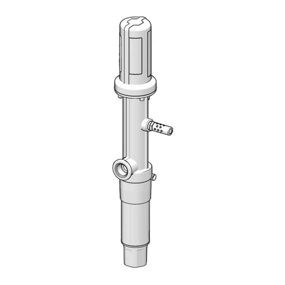
Model 279035
Model 279036
3A9292B
EN
Model 279037
Advertisement
Table of Contents

Related Manuals for Graco Fast-Ball 100


Summary of Contents for Graco Fast-Ball 100
- Page 1 Instructions ® 1:1 Ratio Fast-Ball 100 Pumps 3A9292B For dispensing non-abrasive oils and lubricants only. For professional use only. Not approved for use in explosive atmospheres or hazardous (classified) locations. Models: 279035: Universal Pump 279036: Cut to Length Universal Pump, PVC tube 279037: 55 Gallon (200L) Drum, Universal Pump, steel tube...
- Page 2 Warnings Warnings The following warnings are for the setup, use, grounding, maintenance, and repair of this equipment. The exclamation point symbol alerts you to a general warning and the hazard symbols refer to procedure-specific risks. When these symbols appear in the body of this manual or on warning labels, refer back to these Warnings. Product-specific hazard symbols and warnings not covered in this section may appear throughout the body of this manual where applicable.
- Page 3 WARNING Warnings MOVING PARTS HAZARD Moving parts can pinch, cut or amputate fingers and other body parts. • Keep clear of moving parts. • Do not operate equipment with protective guards or covers removed. • Equipment can start without warning. Before checking, moving, or servicing equipment, follow the Pressure Relief Procedure and disconnect all power sources.
-
Page 4: Typical Installation
Typical Installation Typical Installation . 1: Typical Installation Key: Air shutoff valve Drum pump (Model 279036, 279037) Air filter Fluid drain valve (required, Part No. 210658) Air regulator and gauge Air inlet Air motor lubricator Ball valve (releases collected moisture) Bleed-type master air valve (required, Part No. -
Page 5: Installation
Installation Installation Grounding The equipment must be grounded to reduce the risk of static sparking. Static sparking can cause fumes to ignite or explode. Grounding provides an escape wire for the electric current. Pump: Refer to F . 2 for the following instructions. 1. -
Page 6: Other Accessories
Wall Bracket (J): used for mounting the universal • Thermal relief kit (R): assists in relieving pressure pump. The wall bracket is sized to fit any Graco in the pump, hose, and dispensing valve due to pump designed to use a 2 in. bung adapter (Part heat expansion (Part No. -
Page 7: Operation
Operation Operation Pressure Relief Procedure NOTICE Never allow the pump to run dry of the fluid being Follow the Pressure Relief Procedure whenever pumped. A dry pump quickly accelerates to a high you see this symbol. speed, possibly damaging itself, and it may get very hot. -
Page 8: Recycling And Disposal
Recycling and Disposal Recycling and Disposal End of Product Life At the end of the product’s useful life, dismantle and recycle it in a responsible manner. • Perform the Pressure Relief Procedure, page 7. • Drain and dispose of fluids according to applicable regulations. -
Page 9: Troubleshooting
Troubleshooting Troubleshooting Follow Pressure Relief Procedure, page 7, before checking or repairing the system. NOTE: Check all possible problems and causes before disassembling pump. Problem Cause Solution Pump does not run There is no fluid demand In a closed end system, the pump runs only when there is a demand for fluid. -
Page 10: Air Valve
Refer to Parts, page 12, for the numbers provided in these instructions. Clean and inspect all parts for wear or damage during disassembly. Replace parts as needed. Fast-Ball 100 Repair Kit (Part No. 279038) contains replacement parts. For best results, use all of the parts in the kit. Add moderate grease to the sealing parts during reassembly. - Page 11 Repair 8. Use a wrench to hold the piston rod (15) stationary and reattach the fluid piston valve and torque to 75 to 100 in-lb (8.47 to 11.30 N•m). NOTE: Place the fluid piston (19) flat surface to the flat surface of the fluid piston valve (22).
- Page 12 Parts Parts 3A9292B...
- Page 13 Parts Ref. Part Description Qty. Cylinder, air 157630 Spring, compression 3✿ Air valve 3a❖ Plate, air exhaust valve 3b❖ O-ring 3c❖ O-ring Air piston Screw and spacer Plate, valve Washer 19F530 Spring, compression Shaft Holder, spring Bushing 9❖ O-ring 10❖† O-ring 11❖...
-
Page 14: Performance Chart
Parts Performance Chart To find the fluid outlet pressure at a specific flow and To find pump air consumption at a specific fluid flow operating air pressure: and air pressure: 1. Locate the desired flow along the bottom of the 1. - Page 15 Dimensions Dimensions 3A9292B...
-
Page 16: Technical Specifications
Technical Specifications Technical Specifications 1:1 Ratio Fast-Ball 100 Pump Metric Maximum fluid working pressure 150 psi 1.0 MPa, 10.3 bar Fluid pressure ratio Air pressure operating range 40-150 psi 0.28-1.0 MPa, 2.8-10.3 bar Air consumption at 1 gpm (3.8 lpm) at 100 psi 1.3 scfm... -
Page 17: California Proposition
California Proposition 65 California Proposition 65 CALIFORNIA RESIDENTS WARNING: Cancer and reproductive harm – www.P65warnings.ca.gov. 3A9292B... -
Page 18: Graco Standard Warranty
With the exception of any special, extended, or limited warranty published by Graco, Graco will, for a period of twelve months from the date of sale, repair or replace any part of the equipment determined by Graco to be defective.
Need help?
Do you have a question about the Fast-Ball 100 and is the answer not in the manual?
Questions and answers