Graco Husky 1050HP Operation
Air-operated diaphragm pump
Hide thumbs
Also See for Husky 1050HP:
- Repair parts (46 pages) ,
- Operation (22 pages) ,
- Operation (22 pages)
Table of Contents
Advertisement
Quick Links
Operation
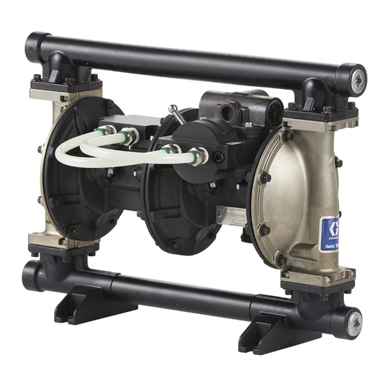
Husky™ 1050HP 2:1
Air-Operated Diaphragm Pump
1–inch high-pressure pump with modular air valve for fluid transfer applications. For professional use
only.
Important Safety Instructions
Read all warnings and instructions in this manual and in your
Repair/Parts manual. Save these instructions.
Maximum Fluid Working Pressure:
250 psi (1.72 MPa, 17.2 bar)
Maximum Air Input Pressure:
125 psi (0.86 MPa, 8.6 bar)
Springer Pumps, LLC
Telford, PA 18969
PROVEN QUALITY. LEADING TECHNOLOGY.
Tel: 866-777-6060 / Int'l: 215-949-2900
Fax: 866-777-6383 / Int'l: 215-721-1296
334014B
EN
shop.springerpumps.com
info@springerpumps.com
Advertisement
Table of Contents

Related Manuals for Graco Husky 1050HP


Summary of Contents for Graco Husky 1050HP
- Page 1 Operation Husky™ 1050HP 2:1 334014B Air-Operated Diaphragm Pump 1–inch high-pressure pump with modular air valve for fluid transfer applications. For professional use only. Important Safety Instructions Read all warnings and instructions in this manual and in your Repair/Parts manual. Save these instructions. Maximum Fluid Working Pressure: 250 psi (1.72 MPa, 17.2 bar) Maximum Air Input Pressure:...
-
Page 2: Table Of Contents
Pressure Relief Procedure......13 Graco Standard Husky Pump Warranty....22 Related Manuals Manual No. Description 334390 Husky 1050HP Air-Operated Diaphragm Pump, Repair/Parts NOTE: For Troubleshooting information, see the Repair/Parts Manual 334390. 334014B Springer Pumps, LLC Tel: 866-777-6060 / Int'l: 215-949-2900 shop.springerpumps.com... -
Page 3: Ordering Information
Quick Reference. Follow the page references on these two pages for further ordering To Order Replacement Parts information, as needed. 2. Please call Graco Customer Service to order. Please call your distributor. 334014B Springer Pumps, LLC Tel: 866-777-6060 / Int'l: 215-949-2900 shop.springerpumps.com... -
Page 4: Configuration Number Matrix
Configuration Number Matrix Configuration Number Matrix Check the identification plate (ID) for the 20–digit Configuration Number of your pump. Use the following matrix to define the components of your pump. Sample Configuration Number: 1050HP A01A SP SP Pump Model Balls Diaphragms Center Section Manifolds... -
Page 5: Warnings
Warnings Warnings The following warnings are for the setup, use, grounding, maintenance, and repair of this equipment. The exclamation point symbol alerts you to a general warning and the hazard symbols refer to procedure-specific risks. When these symbols appear in the body of this manual or on warning labels, refer back to these Warnings. - Page 6 Warnings WARNING EQUIPMENT MISUSE HAZARD Misuse can cause death or serious injury. • Do not operate the unit when fatigued or under the influence of drugs or alcohol. • Do not exceed the maximum working pressure or temperature rating of the lowest rated system component.
- Page 7 Warnings WARNING PLASTIC PARTS CLEANING SOLVENT HAZARD Many solvents can degrade plastic parts and cause them to fail, which could cause serious injury or property damage. • Use only compatible water-based solvents to clean plastic structural or pressure-containing parts. • See Technical Data in this and all other equipment instruction manuals. Read fluid and solvent manufacturer’s MSDSs and recommendations.
-
Page 8: Installation
Mounting securely. Connect the clamp end of the ground wire to a true earth ground. A ground wire and clamp, Part 238909, is available from Graco. • The pump exhaust air may contain contaminants. Ventilate to a remote area. See Air Exhaust Ventilation, page •... -
Page 9: Air Line
Installation Air and fluid hoses: • Use only grounded hoses 2. Locate a bleed-type master air valve (B) close to with a maximum of 500 ft (150 m) combined hose the pump and use it to relieve trapped air. Be length to ensure grounding continuity. -
Page 10: Air Exhaust Ventilation
Installation Air Exhaust Ventilation 2. Install a grounded air exhaust hose (U). Connect the muffler (T) to the other end of the hose. The minimum size for the air exhaust hose is 3/4 in. (19 mm) ID. If a hose longer than 15 ft (4.57 m) is required, use a larger diameter hose. -
Page 11: Fluid Supply Line
Installation Fluid Supply Line Fluid Outlet Line Typical Floor Mount Installation, page 12 Typical Floor Mount Installation, page 1. Use grounded flexible, fluid supply hoses (G). 1. Use grounded, flexible fluid hoses (L). See Grounding, page 8 Grounding, page 8 2. -
Page 12: Typical Floor Mount Installation
Installation Typical Floor Mount Installation Figure 3 Typical floor mount installation Air supply line Fluid drain valve (required) Bleed-type master air valve (required for Fluid shutoff valve pump) Air filter and regulator Flexible fluid outlet hose Air inlet M Fluid inlet (2 ports on aluminum manifolds,1 port on SST manifolds) Master air valve (for accessories) Fluid outlet (2 ports on aluminum manifolds,1... -
Page 13: Operation
Operation Operation Pressure Relief Procedure 4. Open the fluid drain valve (installed on the system) to relieve all fluid pressure. Have a container ready to catch the drainage. Follow the Pressure Relief Procedure whenever you see this symbol. Tighten Fasteners Before Setup Before using the pump for the first time, check and retorque all external fasteners. -
Page 14: Start And Adjust The Pump
Operation Start and Adjust the Pump 9. Slowly increase air pressure with the air regulator until the pump starts to cycle. Allow the pump to cycle slowly until all air is pushed out of the lines 1. Be sure the pump is properly grounded. Refer and the pump is primed. -
Page 15: Maintenance
Maintenance Maintenance Maintenance Schedule Flushing and Storage Establish a preventive maintenance schedule, based on the pump’s service history. Scheduled maintenance is especially important to prevent spills or leakage due to diaphragm failure. • Flush before fluid can dry in the equipment, at the Lubrication end of the day, before storing, and before repairing equipment. -
Page 16: Torque Instructions
Maintenance Torque Instructions NOTE: All fasteners for the fluid covers, center Fluid cover, center diaphragm joint, and manifold diaphragm joint, and manifolds have a thread-locking fasteners: 100 in-lb (11.3 N•m) adhesive patch applied to the threads. If this patch is Lubricate air valve fasteners prior to reassembly to excessively worn, the fasteners may loosen during prevent galling. -
Page 17: Dimensions And Mounting
Dimensions and Mounting Dimensions and Mounting Aluminum Aluminum and SST 12.7 in (323 mm) 11.8 in (300 mm) 6.2 in (157 mm) 14.4 in (366 mm) 12.9 in (328 mm) 9.4 in (239 mm) 15.3 in (389 mm) 13.7 in (348 mm) 15.6 in (396 mm) 10.9 in (277 mm) 9.5 in (241 mm) -
Page 18: Performance Charts
Performance Charts Performance Charts Low Pressure Setting Fluid Pressure Approximate Cycles per Minute (0.86, 8.6) Operating Air Pressure (0.7, 7.0) 125 psi (0.86 MPa, 8.6 bar) (0.52, 5.2) (MPa, bar) 100 psi (0.7 MPa, 7.0 bar) (0.34, 3.4) 70 psi (0.48 MPa, 4.8 bar) (0.17, 1.7) 40 psi (0.28 MPa, 2.8 bar) (38) - Page 19 Performance Charts High Pressure Setting Fluid Pressure Approximate Cycles per Minute (1.72, 17.2) Operating Air Pressure (1.38, 13.8) 125 psi (0.86 MPa, 8.6 bar) (1.03, 10.3) (MPa, bar) 100 psi (0.7 MPa, 7.0 bar) (0.7, 7.0) 70 psi (0.48 MPa, 4.8 bar) (0.34, 3.4) 40 psi (0.28 MPa, 2.8 bar) (38)
-
Page 20: Technical Data
Technical Data Technical Data Metric Maximum fluid working pressure 250 psi 1.72 MPa,17.2 bar Air pressure operating range 20-125 psi 0.14-0.86 MPa, 1.4-8.6 bar Fluid displacement per cycle Low Pressure Setting 0.17 g 0.64 l High Pressure Setting 0.20 g 0.76 l Air consumption at 70 psi, 20 gpm... -
Page 21: Fluid Temperature Range
Technical Data Sound Power (measured per ISO-9614–2) At 70 psi (0.48 MPa, 4.8 bar) and 50 cpm Low Pressure Setting 78 dBa High Pressure Setting 91 dBa At 100 psi (0.7 MPa, 7.0 bar) and full flow Low Pressure Setting 90 dBa 102 dBa High Pressure Setting... -
Page 22: Graco Standard Husky Pump Warranty
With the exception of any special, extended, or limited warranty published by Graco, Graco will, for a period of five years from the date of sale, repair or replace any part of the equipment determined by Graco to be defective. This warranty applies only when the equipment is installed, operated and maintained in accordance with Graco’s written recommendations.
Need help?
Do you have a question about the Husky 1050HP and is the answer not in the manual?
Questions and answers