Table of Contents
Advertisement
Quick Links
Instructions – Parts List
STAINLESS STEEL
Check-Matet 1000 Pumps
With Priming Piston, and Severe-Duty Rod and Cylinder
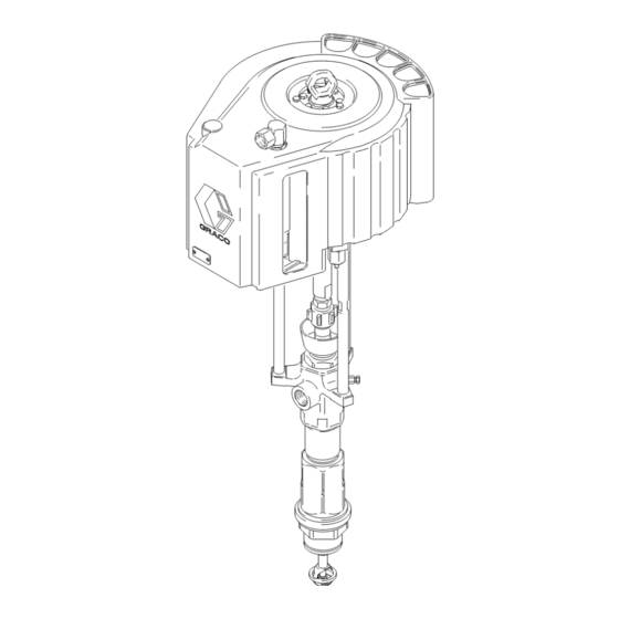
Part No. 237708 Pump, Series B,
50:1 Ratio, with Kingt Air Motor
34.5 MPa, 345 bar (5000 psi) Maximum Fluid Working Pressure
0.7 MPa, 7 bar (100 psi) Maximum Air Input Pressure
Part No. 237520 Pump, Series A,
80:1 Ratio, with Premiert Air Motor
40.3 MPa, 403 bar (5850 psi) Maximum Fluid Working Pressure
0.5 MPa, 5 bar (73 psi) Maximum Air Input Pressure
US Patent Nos. 5,147,188 and 5,154,532.
Other Patents Pending.
Important Safety Instructions
Read all warnings and instructions
in this manual. Save these instructions.
See page 2 for Table of Contents.
GRACO INC. P.O. BOX 1441 MINNEAPOLIS, MN 55440-1441
Copyright 1997, Graco Inc. is registered to I.S. EN ISO 9001
Parts
Model 237520
308356E
Model 237708
05014B
03820
Advertisement
Table of Contents

Related Manuals for Graco Check-Mate 1000


Summary of Contents for Graco Check-Mate 1000
- Page 1 Read all warnings and instructions in this manual. Save these instructions. See page 2 for Table of Contents. 03820 Model 237520 05014B GRACO INC. P.O. BOX 1441 MINNEAPOLIS, MN 55440-1441 Copyright 1997, Graco Inc. is registered to I.S. EN ISO 9001...
-
Page 2: Table Of Contents
......This symbol alerts you to the possibility of damage to Graco Standard Warranty ..... . -
Page 3: Warnings
D This equipment is for professional use only. D Read all instruction manuals, tags, and labels before operating the equipment. D Use the equipment only for its intended purpose. If you are not sure, contact your Graco distributor. D Do not alter or modify this equipment. - Page 4 WARNING INJECTION HAZARD Spray from the spray gun/dispense valve, leaks or ruptured components can inject fluid into your body and cause extremely serious injury, including the need for amputation. Fluid splashed in the eyes or on the skin can also cause serious injury. D Fluid injected into the skin might look like just a cut, but it is a serious injury.
- Page 5 WARNING FIRE AND EXPLOSION HAZARD Improper grounding, poor ventilation, open flames or sparks can cause a hazardous condition and result in a fire or explosion and serious injury. D Ground the equipment and the object being sprayed. Refer to Grounding on page 6. D If there is any static sparking or you feel an electric shock while using this equipment, stop spray- ing/dispensing immediately.
-
Page 6: Installation
Installation Grounding WARNING FIRE AND EXPLOSION HAZARD Before operating the pump, ground the system as explained below. Also read the section FIRE OR EXPLOSION HAZ- ARD on page 5. 0864 1. King Pumps: use a ground wire and clamp. See Fig. - Page 7 Pump 200 Liter (55 Gallon) Air-Powered Ram Accessories are available from Graco. If you supply Main Air Bleed Valve (required, for pump and ram) your own accessories, be sure they are adequately Air Line Lubricator (position only) sized and pressure-rated to meet the system’s require-...
- Page 8 Installation D A pump air bleed valve (E) is required in your System Accessories system to relieve air trapped between it and the air motor when the valve is closed (see the WARNING WARNING at left). Be sure the bleed valve is easily accessible from the pump, and is located downstream from A main air bleed valve (C), pump air bleed valve the air regulator.
-
Page 9: Operation/Maintenance
Operation Pressure Relief Procedure Packing Nut/Wet-Cup Before starting, fill the packing nut (2) 1/3 full with Graco Throat Seal Liquid (TSL) or compatible solvent. WARNING See Fig. 4. INJECTION HAZARD WARNING The system pressure must be manually relieved to prevent the system from starting or spraying accidentally. - Page 10 Operation Flush the Pump Before First Use WARNING INJECTION HAZARD The pump is tested with lightweight oil, which is left in To reduce the risk of fluid injection, do not use to protect the pump parts. If the fluid you are using your hand or fingers to cover the bleed hole on the may be contaminated by the oil, flush it out with a underside of the bleeder valve body (29) when...
- Page 11 Operation Shutdown and Care of the Pump Flush with a fluid that is compatible with the fluid you are pumping and with the wetted parts in your system. Check with your fluid manufacturer or supplier for WARNING recommended flushing fluids and flushing frequency. Always flush the pump before fluid dries on the dis- To reduce the risk of serious injury whenever you placement rod.
-
Page 12: Troubleshooting
Turn on the air just enough to start the pump. If the pump starts when the air is turned on, the obstruction is in the fluid hose or gun. NOTE: If you experience air motor icing, contact your Graco distributor. 308356... - Page 13 Troubleshooting PROBLEM CAUSE SOLUTION Pump operates, but Fluid too heavy for pump priming. Use the bleeder valve (see page 10); use a ram. output low on down- stroke. Held open or worn intake valve or seals. Clear the valve; replace the seals. Pump operates, but Held open or worn piston valve or seals.
-
Page 14: Required Tools
Service Required Tools 5. Using an adjustable wrench (or a hammer and rod), unscrew the coupling nut (104) from the D Torque wrench motor shaft (Z, Model 237708) or adapter (107, D Bench vise, with soft jaws Model 237520). Do not lose or drop the coupling collars (105). - Page 15 Fill the wet-cup (2) 1/3 full of Pressure Relief Procedure on page 9. Graco Throat Seal Liquid or compatible solvent. 9. Before returning the pump to production, relieve 8. Turn on the air supply. Run the pump slowly to the pressure and retorque the packing nut (2) to ensure proper operation.
-
Page 16: Displacement Pump Service
Displacement Pump Service Disassembly NOTE: These instructions are written with the pump separating at joint A. If it separates at joints B or C, When disassembling the pump, lay out all the removed disassemble it at that joint, place the intake housing parts in sequence, to ease reassembly. - Page 17 Displacement Pump Service 6. Pull the intake seat (37) and seal (38) out the bottom of the intake valve housing (17). Take care not to drop the check valve assembly (V) as it comes free, and set it aside for later. See Fig. 6. NOTE: If the seat (37) is difficult to remove, insert a See Fig.
- Page 18 Displacement Pump Service 9. Remove the seal (8) from the bottom of the cylin- NOTE: The seal (39) is press-fit in the nut (15) and der (10). See Fig. 11. Shine a light into the cylinder may require cutting to ease removal. to examine the inside surface for scoring or dam- age.
- Page 19 Displacement Pump Service Reassembly 4. Lubricate the piston seal (13*) and install it on the piston seat (14). Screw the piston guide (11) onto the seat (14). Place the guide in a vise as shown in Fig. 14 shows a cutaway of the entire pump. Fig.
- Page 20 Displacement Pump Service 7. If the cylinder (10) was removed from the outlet 11. Lubricate the seal (8*) and install it on the bottom housing (9), lubricate the seal (8*) and place it on of the cylinder (10). Slide the intake valve housing the top of the cylinder.
- Page 21 Displacement Pump Service THROAT PACKING DETAIL Piston check valve (see Fig. 11). Intake check valve (see Fig. 12). Lubricate. Lips of v-packings must face down. Screw valve plug (20) completely into valve body (29). Torque to 136–149 N.m (100–110 ft-lb). Torque to 203–237 N.m (150–175 ft-lb).
- Page 22 Displacement Pump Service 15. Screw the intake cylinder (19) into the intake 17. Check that the flats of the priming piston rod (18) housing (17). Using a pipe wrench on the hex of are accessible below the intake cylinder (19). If the cylinder (19), torque the cylinder to 522–542 not, tap on the top of the displacement rod (1) with N.m (385–400 ft-lb).
- Page 23 Notes 308356...
-
Page 24: Parts
Parts Part No. 237708 Pump, Series B, 50:1 Ratio, with King Air Motor Ref. Part No. Description Qty. 245111 AIR MOTOR, King See 309347 for parts 190000 ROD, tie; 224 mm (8.82 in.) shoulder to shoulder 106166 NUT, hex; M16 x 2.0 186925 NUT, coupling 184129... - Page 25 Parts Part No. 237520 Pump, Series A, 80:1 Ratio, with Premier Air Motor Ref. Part No. Description Qty. 222800 AIR MOTOR, Premier See 308213 for parts 184381 ROD, tie; 560 mm (22.1 in) shoulder to shoulder 106166 NUT, hex; M16 x 2.0 184098 NUT, coupling 184129...
- Page 26 Displacement Pump Parts Model 236613, Series A Displacement Pump 05012 308356...
- Page 27 Displacement Pump Parts Model 236613, Series A Displacement Pump Part Part Description Description 184487 ROD, displacement; stainless steel 237979 HOUSING, intake; stainless steel 236582 PACKING NUT/WET-CUP; 184490 ROD, priming piston; stainless steel stainless steel 189516 CYLINDER, intake; stainless steel 189645 HOUSING, throat packing;...
-
Page 28: Technical Data And Performance Chart
Technical Data (Model 237708 King Pump) WARNING Be sure that all fluids and solvents used are chemically compatible with the Wetted Parts listed below. Always read the manufacturer’s literature before using fluid or solvent in this pump. Ratio ............... 50:1 Maximum fluid working pressure . - Page 29 Technical Data Model 237520 Premier Pump WARNING Be sure that all fluids and solvents used are chemically compatible with the Wetted Parts listed below. Always read the manufacturer’s literature before using fluid or solvent in this pump. Ratio ............... 80:1 Maximum fluid working pressure .
- Page 30 Notes 308356...
-
Page 31: Dimensions
Dimensions and Mounting Hole Layout Model 237708 Shown King Pumps 94.28 mm (3.712 in.) 101.6 mm 94.28 mm (4.0 in.) (3.712 in.) 50.8 mm (2.0 in.) Three M16 x 2.0 Holes 11.1 mm (0.437 in.) 88 mm DIA (4) (3.464 in.) 0653 Premier Pumps 135.0 mm... -
Page 32: Graco Standard Warranty
With the exception of any special, extended, or limited warranty published by Graco, Graco will, for a period of twelve months from the date of sale, repair or replace any part of the equipment determined by Graco to be defective.
Need help?
Do you have a question about the Check-Mate 1000 and is the answer not in the manual?
Questions and answers