Table of Contents
Advertisement
Quick Links
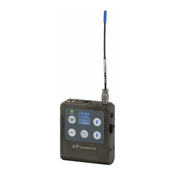
LT/E01
Synthesized UHF Belt-Pack Transmitter
Featuring
Digital Hybrid Wireless
Technology
US Patent 7,225,135
Quick Start Steps
1) Install good batteries and turn power on (see pages
6 and 7).
2) Set the compatibility mode to match the receiver
(see page 11).
3) Connect the signal source and adjust input gain for
optimum modulation level (see page 12).
4) Set Step Size and frequency to match receiver
(see page 12). Also see receiver manual for scan-
ning procedure to find a clear operating frequency.
5) Turn on the receiver and verify that solid RF and
audio signals are present (see receiver manual).
Fill in for your records:
Serial Number:
Purchase Date:
®
INSTRUCTION MANUAL
Rio Rancho, NM, USA
www.lectrosonics.com
Advertisement
Table of Contents

Related Manuals for Lectrosonics LT/E01


Summary of Contents for Lectrosonics LT/E01
-
Page 1: Quick Start Steps
INSTRUCTION MANUAL LT/E01 Synthesized UHF Belt-Pack Transmitter Featuring Digital Hybrid Wireless ® Technology US Patent 7,225,135 Quick Start Steps 1) Install good batteries and turn power on (see pages 6 and 7). 2) Set the compatibility mode to match the receiver (see page 11). - Page 2 LT/E01 LECTROSONICS, INC.
-
Page 3: Table Of Contents
LectroRM .......................................15 5-Pin Input Jack Wiring ..................................16 Microphone Cable Termination for Non-Lectrosonics Microphones .............................17 Input Jack Wiring for Different Sources .............................18 Compatible Wiring for Both Servo Bias Inputs and Earlier Transmitters: ....................18 Simple Wiring for Servo Bias Inputs ONLY: ............................18 Microphone RF Bypassing ..................................19... -
Page 4: Introduction
The input standard Lectrosonics 25.6 MHz bands, except band jack is a standard Lectrosonics 5-pin type for use with electret lavaliere mics, dynamic mics, musical instru- 606. Frequencies are displayed on the LCD in MHz and in a hex code used with earlier Lectrosonics equipment. -
Page 5: Dsp-Controlled Input Limiter
Digital Hybrid Wireless Belt-Pack Transmitter DSP-controlled Input Limiter Pilot Tone Squelch The squelch system in a receiver is a method of muting The transmitter employs a digitally-controlled analog audio limiter prior to the analog-to-digital converter. the audio when the RF signal conditions are too poor The limiter has a range greater than 30 dB for excellent to produce usable audio. -
Page 6: Battery Installation
LT/E01 Battery Installation The transmitter is powered by two AA batteries. We If the batteries are inserted incorrectly, the door will recommend using alkaline, lithium, or rechargeable close but the unit will not operate. batteries for longest life. Standard zinc-carbon batteries The battery contacts can be cleaned with alcohol and marked “heavy-duty”... -
Page 7: Operating Instructions
LCD. NOTE: The battery timer feature in many When alkaline or lithium batteries are being used, the Lectrosonics receivers is very helpful in measuring LED labeled BATT on the keypad glows green when the battery runtime when using rechargeable batteries. -
Page 8: Powering On In Standby Mode
LT/E01 Powering On in Standby Mode Entering the Power Menu A brief press of the Power Button , releasing it before Press the power button from any menu or screen the counter has reached 3, will turn the unit on with the and a menu with appear with several options. -
Page 9: Lcd Menu Map
Digital Hybrid Wireless Belt-Pack Transmitter LCD Menu Map Gain Use arrow keys to Gain Select from select input gain listing BACK Polarity Line Use arrow keys to select LineIn Instr. audio output polarity BACK Use arrow keys Press SEL to Freq Freq. -
Page 10: Main Menu And Setup Screen Details
LT/E01 Main Menu and Setup Main Window Indicators The Main Window displays the band number, Standby Screen Details or Operating mode, operating frequency, audio level, battery status and programmable switch function. When the frequency step size is set at 100 kHz, the LCD will Locking/Unlocking Changes to Settings look like the following. -
Page 11: Selecting The Compatibility (Compat) Mode
Digital Hybrid receivers. The receiver must also be set to the Digital Hybrid compatibility mode. If the programmable switch function is set for Talkback, IFB Series works with Lectrosonics IFB R1/R1a analog the Main Window will indicate that the function is en- receivers. -
Page 12: Adjusting The Input Gain
Green Normally, the receiver is used to find a clear operat- Greater than +10 dB ing frequency. All Lectrosonics Digital Hybrid Wireless ® receivers provide a scanning function to quickly and NOTE: Full modulation is achieved at 0 dB, when the “-20”... -
Page 13: Selecting Frequency Using Two Buttons
RF signals are present at different battery life rather than the indicators on the transmitter. levels, and areas where there is little or no RF energy The timer is available on all Lectrosonics Digital Hybrid present. The software then automatically selects the Wireless receivers. -
Page 14: Enabling Remote Control
Enabling Remote Control IR Sync Operation Transmitter settings can be configured using special A Lectrosonics receiver with IR Sync capability can tones generated by a smartphone using a remote transfer the settings for Frequency, Step Size and Com- control application such as Lectro RM (available on the patibility mode to the transmitter via the IR ports. -
Page 15: Lectrorm
Each version also has a remote control activation. mechanism to prevent accidental activation of the tone. Please be aware this app is not a Lectrosonics product. It is privately owned and operated by New Endian LLC, www.newendian.com. -
Page 16: 5-Pin Input Jack Wiring
LT/E01 5-Pin Input Jack Wiring Audio input jack wiring: The wiring diagrams included in this section represent the basic wiring necessary for the most common types PIN 1 of microphones and other audio inputs. Some micro- Shield (ground) for positive biased electret lavaliere phones may require extra jumpers or a slight variation microphones. -
Page 17: Microphone Cable Termination For Non-Lectrosonics Microphones
VHF transmitters with 5-pin shield jacks require a different termination. Lectrosonics lavaliere microphones are terminated for compatibility with VHF and UHF transmitters, which is different from what is shown here. Rio Rancho, NM... -
Page 18: Input Jack Wiring For Different Sources
In addition to the microphone and line level wiring hook- A lot of information regarding microphone wiring is also ups illustrated below, Lectrosonics makes a number of available in the FAQ section of the web site at: cables and adapters for other situations such as con- http://www.lectrosonics.com... -
Page 19: Microphone Rf Bypassing
Line Level More Headroom Use 330 pF capacitors. Capacitors are available from (20 dB) Lectrosonics. Please specify the part number for the desired lead style. Leaded capacitors: P/N 15117 Leadless capacitors: P/N SCC330P All Lectrosonics lavaliere mics are already bypassed and do not need any additional capacitors installed for proper operation. -
Page 20: Accessories
LT/E01 Accessories Specifications and Features BCSLEBN Spring-loaded belt clip Operating Frequencies: Band A1: 470.100 - 537.575 Band B1: 537.600 - 614.375 Band 606: 606.000 - 631.500 LTBATELIM Battery eliminator; allows transmitter Band C1: 614.400 - 691.175 to be operated from external power;... -
Page 21: Troubleshooting
Digital Hybrid Wireless Belt-Pack Transmitter Troubleshooting It is important that you follow these steps in the sequence listed. Symptom: Possible Cause: Transmitter Battery LED off 1. Batteries are inserted incorrectly. when Power Switch “ON” 2. Batteries are low or dead. No Transmitter Modulation LEDs 1. -
Page 22: Service And Repair
LECTROSONICS’ Service Department is equipped and staffed to quickly repair your equipment. In warranty repairs are made at no charge in accordance with the terms of the warranty. Out-of-warranty repairs are charged at a modest flat rate plus parts and shipping. - Page 23 Digital Hybrid Wireless Belt-Pack Transmitter Rio Rancho, NM...
-
Page 24: Firmware Update
Windows operating system with the transmitter connected to a computer via the USB port. Go to www.lectrosonics.com/US. In the top menu, hover the mouse over Support, and click on Wireless Support. On the right-hand-side Wireless Support Menu, choose Wireless Downloads. - Page 25 Step 7: Refer to Step 1 to return to Firmware web page. Down- In Lectrosonics USB Firmware Updater, choose the load Firmware Update and save to a local file on your detected device, browse to local Firmware File and click PC for easy locating when updating.
- Page 26 LT/E01 LECTROSONICS, INC.
- Page 27 Digital Hybrid Wireless Belt-Pack Transmitter Rio Rancho, NM...
- Page 28 This warranty does not apply to used or demonstrator equipment. Should any defect develop, Lectrosonics, Inc. will, at our option, repair or replace any defective parts without charge for either parts or labor. If Lectrosonics, Inc. cannot correct the defect in your equipment, it will be replaced at no charge with a similar new item.
Need help?
Do you have a question about the LT/E01 and is the answer not in the manual?
Questions and answers