Table of Contents

Subscribe to Our Youtube Channel
Related Manuals for Lectrosonics LMa


Summary of Contents for Lectrosonics LMa
- Page 1 INSTRUCTION MANUAL Synthesized UHF Belt-Pack Transmitter Featuring Digital Hybrid Wireless Technology ® US Patent 7,225,135 Fill in for your records: Serial Number: Purchase Date: Rio Rancho, NM, USA www.lectrosonics.com...
- Page 2 LECTROSONICS, INC.
-
Page 3: Table Of Contents
Adjusting the Transmitter Frequency ..............................8 5-Pin Input Jack Wiring ..................................9 Installing the Connector: ..................................9 Microphone Cable Termination for Non-Lectrosonics Microphones ....................10 Wiring Hookups for Different Sources ...............................11 Compatible Wiring for Both Servo Bias Inputs and Earlier Transmitters: ....................11 Simple Wiring - Can ONLY be used with Servo Bias Inputs: .......................11 Microphone RF Bypassing ..................................12... -
Page 4: Introduction
DSP “compatibility modes” allow signal to use a noisy channel as efficiently and robustly the LMa to be used with a variety of analog receivers as possible, yielding audio performance that rivals that in addition to its native hybrid mode by emulating the... -
Page 5: Lma Block Diagram
RF signal is present on the carrier frequency of the system. The pilot tone also eliminates noise (pops, thumps, etc.) from occurring when the transmitter is powered on and off. LMa Block Diagram Battery Bicolor Power... -
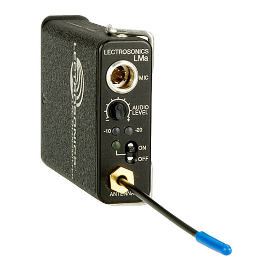
Page 6: Controls And Functions
Contact a Lectrosonics sales represen- instrument. These two bicolor LEDs can glow either red tative, or visit our web site (www.lectrosonics.com) for or green to indicate modulation levels. more details. -
Page 7: Battery Installation
LiPolymer batter- ies. However, it may be possible to track battery status using the Battery Timer function available in a number of Lectrosonics receivers. (Refer to the associated receiver manual to determine if this function is available in your situation.) -
Page 8: Operating Instructions
Operating Instructions Selecting the Compatibility Mode Frequency Select Switch Settings (C,C) 1.6M 100K The LMa transmitter is capable of working with Lec- trosonics 400 Series Digital Hybrid Wireless , 200 ® Series analog, 100 Series analog and some non-Lec- trosonics analog wireless receivers (contact the factory for details). -
Page 9: Adjusting The Transmitter Frequency
-20 dB to -10 dB Green receiver’s display. -10 dB to +0 dB Green Green The R400A, Venue Series and other Lectrosonics receivers have an automatic scanning function called +0 dB to +10 dB Green SmartTune that automatically locates clear operat- Greater than +10 db ing channels. -
Page 10: 5-Pin Input Jack Wiring
TA5F to your particular microphone. (See Wiring Diagrams below.) A length of .065 OD clear tubing is included if insulating the resistor leads or shield wire is necessary. (Remove rubber strain relief from connector backshell by pulling it out of the backshell.) LECTROSONICS, INC. -
Page 11: Microphone Cable Termination For Non-Lectrosonics Microphones
VHF transmitters with 5-pin shield jacks require a different termination. Lectrosonics lavaliere microphones are terminated for compatibility with VHF and UHF transmitters, which is different than what is shown here. Rio Rancho, NM... -
Page 12: Wiring Hookups For Different Sources
Sanken COS-11. Simplified wiring for microphones such as negative bias TRAM. This wiring is fully compatible with 5-pin inputs on Lectrosonics NOTE: This servo bias wiring is not compatible with earlier transmitters such as the LM and UM Series. This is the wiring versions of Lectrosonics transmitters. -
Page 13: Microphone Rf Bypassing
Lectrosonics transmitters with 5-pin Preferred locations for bypass capacitors input connectors. The low frequency roll-off in the LMa SHIELD will be set to 35 Hz automatically when these cables SHIELD are connected. -
Page 14: Troubleshooting
LECTROSONICS, INC. -
Page 15: Specifications And Features
Frequency Selection: 256 frequencies in 100 kHz steps Channel Separation: 100 kHz Compatibility Modes: Lectrosonics Digital Hybrid (400 Series), 200 Series, 100 Series, and IFB. Mode 3, Mode 6 (Other brands). RF Power output: 50 mW Pilot tone: 25 to 32 kHz frequency; 5 kHz deviation (400 Series only) Frequency stability: ±... - Page 16 5. Musical instrument volume set too low. Excessive Feedback (With Microphone) 1. Transmitter gain (audio level) too high. Check gain adjustment and/or reduce receiver output level. 2. Microphone too close to speaker system. 3. Microphone is too far from user’s mouth. LECTROSONICS, INC.
-
Page 17: Service And Repair
LECTROSONICS’ Service Department is equipped and staffed to quickly repair your equipment. In warranty repairs are made at no charge in accordance with the terms of the warranty. Out-of-warranty repairs are charged at a modest flat rate plus parts and shipping. - Page 18 LECTROSONICS, INC.
- Page 19 Frequency-Agile UHF Belt-Pack Transmitter Rio Rancho, NM...
-
Page 20: Limited One Year Warranty
This warranty does not apply to used or demonstrator equipment. Should any defect develop, Lectrosonics, Inc. will, at our option, repair or replace any defective parts without charge for either parts or labor. If Lectrosonics, Inc. cannot correct the defect in your equipment, it will be replaced at no charge with a similar new item.
Need help?
Do you have a question about the LMa and is the answer not in the manual?
Questions and answers