Table of Contents
Advertisement
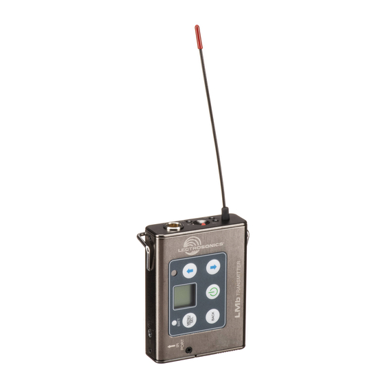
LMb
Synthesized UHF Belt-Pack Transmitter
Fill in for your records:
Serial Number:
Purchase Date:
INSTRUCTION MANUAL
Featuring
Digital Hybrid Wireless
Technology
US Patent 7,225,135
Quick Start Steps
1) Install good batteries and turn power on (see pages
5 and 6).
2) Set compatibility mode to match the receiver (see
page 9).
3) Connect signal source and adjust input gain for
optimum modulation level (see page 9).
4) Set StepSize and frequency to match receiver (see
page 10). Also see receiver manual for scanning
procedure.
5) Turn on the receiver and verify RF and audio sig-
nals are present (see receiver manual).
®
Rio Rancho, NM, USA
www.lectrosonics.com
Advertisement
Table of Contents

Related Manuals for Lectrosonics LMb


Summary of Contents for Lectrosonics LMb
- Page 1 10). Also see receiver manual for scanning procedure. 5) Turn on the receiver and verify RF and audio sig- nals are present (see receiver manual). Fill in for your records: Serial Number: Purchase Date: Rio Rancho, NM, USA www.lectrosonics.com...
-
Page 2: Table Of Contents
About Digital Hybrid Wireless ..........3 Frequency Agility..............3 Wide-Band Deviation ............3 Servo Bias Input and Wiring ..........3 LMb Block Diagram .............. 4 DSP-controlled Input Limiter ..........4 No Pre-Emphasis/De-Emphasis .......... 4 Pilot Tone Squelch ............... 4 Battery Installation ..............5 Belt Clips ................ -
Page 3: Introduction
Hybrid Wireless ® enjoys all the benefits of conventional LMb to also be used with a variety of analog receivers FM wireless systems, such as excellent range, efficient by emulating the compandors found in earlier Lectro- use of RF spectrum, and long battery life. -
Page 4: Lmb Block Diagram
(HF boost) in the transmitter and de-emphasis (HF roll off) in the receiver. Thus, the potential distortion problems associated with pre-em- phasis and de-emphasis are eliminated. LMb Block Diagram Servo Bias Bias Voltage Supply 0, 2 or 4V... -
Page 5: Battery Installation
Digital Hybrid Wireless Belt-Pack Transmitter Battery Installation The transmitter is powered by two AA batteries. We close but the unit will not operate. recommend using alkaline, lithium, or rechargeable The battery contacts can be cleaned with alcohol and batteries for longest life. Standard zinc-carbon batteries a cotton swab, or a clean pencil eraser. -
Page 6: Operating Instructions
Battery Status LED Indicators Alkaline, lithium or rechargeable batteries can be used NOTE: The battery timer feature in many Lectrosonics receivers is very helpful in measuring to power the transmitter. The type of batteries in use are battery runtime when using rechargeable batteries. -
Page 7: Powering On In Standby Mode
Digital Hybrid Wireless Belt-Pack Transmitter Powering On in Standby Mode Locking/Unlocking Changes to Settings A brief press of the Power Button , releasing it before Changes to the settings can be locked. the counter has reached 3, will turn the unit on with the RF output turned off. -
Page 8: Selecting Programmable Switch Functions
1/2 = .050 MHz increased by 25 494.525 The TB icon will b 19 kHz from the upper 3/4 = .075 MHz change when example. Talkback is active 494.500 Top Panel LED will glow blue when Talkback is active LECTROSONICS, INC. -
Page 9: Selecting The Compatibility (Compat) Mode
Digital Hybrid Wireless Belt-Pack Transmitter Selecting the Compatibility (Compat) Mode Adjusting the Input Gain When used with a Lectrosonics Digital Hybrid Wireless The two bicolor Modulation LEDs on the control panel ® receiver, the best audio quality will be achieved with the and keypad provide a visual indication of the audio system set to the Hybrid compatibility mode. -
Page 10: Selecting Step Size
Helpful Features on Receivers a different increment. The increments are also different in the 25 kHz mode from the 100 kHz mode. To aid in finding clear frequencies, several Lectrosonics receivers offer a SmartTune feature that scans the tun- Freq. -
Page 11: About Overlapping Frequency Blocks
494.500 494.500 they reach the end of operation. The timer is available on all Lectrosonics Digital Hybrid Wireless receivers. ® Selecting Audio Polarity (Phase) Restoring Default Settings Audio polarity can be inverted at the transmitter so the This is used to restore the factory settings. -
Page 12: 5-Pin Input Jack Wiring
5) Solder the wires and resistors to the pins on the insert according to the diagrams shown in Wiring Hookups for Different Sources. A length of .065 OD clear tubing is included if you need to insulate the resistor leads or shield wire. LECTROSONICS, INC. -
Page 13: Microphone Cable Termination For Non-Lectrosonics Microphones
VHF transmitters with 5-pin shield jacks require a different termination. Lectrosonics lavaliere microphones are terminated for compatibility with VHF and UHF transmitters, which is different from what is shown here. Rio Rancho, NM... -
Page 14: Input Jack Wiring For Different Sources
Lectrosonics transmitters. Check with the factory Sanken COS-11. to confirm which models can use this wiring. This wiring is fully compatible with 5-pin inputs on Lectrosonics transmitters such as the LM and UM Series. This is the wiring Fig. 11 for the Lectrosonics M152 lavaliere microphone. -
Page 15: Microphone Rf Bypassing
Wiring Diagram for MI39A Instrument Cable Use 330 pF capacitors. Capacitors are available from Lectrosonics. Please specify the part number for the The MI39ARA and MI39AST instrument cable assem- desired lead style. blies allow an optimum match between musical instru-... -
Page 16: Accessories
Instrument cable; active type for use with most instrument pickups; straight 1/4” plug MC35 Line level adapter cable; XLR-F to TA5F; 37” length MC41 Dynamic mic level adapter cable; XLR-F to TA5F; 37” length P/N 55008 AA battery caddy; 4-pack; blue LECTROSONICS, INC. -
Page 17: Troubleshooting
Digital Hybrid Wireless Belt-Pack Transmitter Troubleshooting It is important that you follow these steps in the sequence listed. Symptom: Possible Cause: Transmitter Battery LED off 1. Batteries are inserted incorrectly. when Power Switch “ON” 2. Batteries are low or dead. No Transmitter Modulation LEDs 1. -
Page 18: Specifications And Features
For body worn operation, this transmitter model has been tested and meets the FCC RF exposure guidelines when used with the Lectrosonics accessories supplied or designated for this product. Use of other accessories may not ensure compliance with FCC RF exposure guidelines. Contact Lectrosonics if you have any questions or need more information about RF exposure using this product.. -
Page 19: Service And Repair
LECTROSONICS’ Service Department is equipped and staffed to quickly repair your equipment. In warranty repairs are made at no charge in accordance with the terms of the warranty. Out-of-warranty repairs are charged at a modest flat rate plus parts and shipping. -
Page 20: Limited One Year Warranty
This warranty does not apply to used or demonstrator equipment. Should any defect develop, Lectrosonics, Inc. will, at our option, repair or replace any defective parts without charge for either parts or labor. If Lectrosonics, Inc. cannot correct the defect in your equipment, it will be replaced at no charge with a similar new item.
Need help?
Do you have a question about the LMb and is the answer not in the manual?
Questions and answers