Table of Contents
Advertisement
Quick Links
Advertisement
Table of Contents

Related Manuals for Lectrosonics Dante M2T/E01


Summary of Contents for Lectrosonics Dante M2T/E01
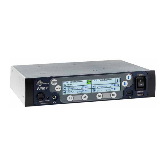
- Page 1 INSTRUCTION MANUAL M2T/E01and M2T/E01/ND Digital IEM Transmitter M2T/E01 Dante M2T/E01 Non Dante This manual is for all 1.X versions of Duet Firmware. Fill in for your records: Serial Number: Purchase Date: Rio Rancho, NM, USA www.lectrosonics.com...
- Page 2 M2T/E01 LECTROSONICS, INC.
-
Page 3: Table Of Contents
Digital IEM Transmitter Table of Contents Introduction ......................................4 What is Dante? .....................................4 System Setup Procedures ..................................5 Summary of Steps ....................................5 Panels and Features ....................................6 M2T/E01 Front Panel ....................................6 M2T/E01 Back Panel ....................................6 Operating Instructions ..................................7 IR (infrared) Port ....................................7 USB Port .......................................7 Headphone Volume Adjustment ................................7 Dante Ports (optional) ...................................7 Ethernet Port ......................................7... -
Page 4: Introduction
The M2T/E01 is designed and developed with the video, control, monitoring professional touring, installation, theater and broadcast customers in mind. The transmitter chassis is all-metal. • Uses inexpensive, off-the-shelf computer The front panel is an aluminum extrusion with a durable networking equipment powder coat finish. LECTROSONICS, INC. -
Page 5: System Setup Procedures
Digital IEM Transmitter System Setup Procedures Summary of Steps 1) Connect power using supplied DCR15/4AU power supply. 2) Power receiver and scan RF spectrum on site. 3) Sync Scan to transfer information from receiver to transmitter. 4) Tune transmitter to unoccupied channels in scan. 5) Sync receiver (refer to receiver manual). -
Page 6: Panels And Features
Power switch buttons previous screen Headphone Volume Headphone Jack USB Port IR Port Adjustment Channel Function Buttons/ Auick Sync M2T/E01 Back Panel Antenna Antenna Jack Dante Ports (optional) Jack XLR/TRS Combo Analog Ethernet Port Input Connectors Power Inlet LECTROSONICS, INC. -
Page 7: Operating Instructions
Digital IEM Transmitter Operating Instructions Power Screens When powering on the M2T/E01, there are three IR (infrared) Port screens that appear in the following order, Duet, Lectro- Settings, including frequency, name, limiter, mix mode, sonics, RF On/Off.: etc. can be transferred to and from the M2T/E01 trans- mitter via this port to an IR enabled receiver to simplify setup. -
Page 8: Lcd Menu Map
Use arrow keys Press SEL to DEFAULTS to select yes DEFAULTS BACK execute or no ABOUT No selections available; for ABOUT BACK information purposes only LINKS LINKS No selections available; use phone to scan QR code BACK for more information LECTROSONICS, INC. -
Page 9: Menu Item Descriptions
Digital IEM Transmitter Menu Item Descriptions Sync Settings Allows sending or retrieving setup data via IR port. RF Enable/Level Allows RF transmission to be turned on and off and set RF levels at 10, 25 or 50 mW. RF Tuning Allows manual selection of the operating frequency. -
Page 10: Audio Level/Trim
The headphone source can be selected here or on the in a rack. front panel, using the A1, A2, B1 or B2 Buttons. • Use UP and DOWN Arrows to select letters and MENU/SEL to set and move cursor. LECTROSONICS, INC. -
Page 11: Restore Defaults
About Displays general information about the M2T/E01, including serial number, and the hardware, FPGA and microcontroller firmware versions. Links QR codes with links to the Lectrosonics website, the M2T/E01 User Manual online and YouTube video tutori- als. Rio Rancho, NM... -
Page 12: Hardware Installation
(25990) Bracket rear tie • (25991) Bracket front tie • (27076) Rack flange bracket • (27082) Rack handle • (28885) (4) SCR10 cap screw • (35664) (4) Rubber foot large • (35959) Hole plug • (A500RA20) (2) Antenna LECTROSONICS, INC. -
Page 13: Iinstalling Two M2T/E01S Into A Single Rack Space
Digital IEM Transmitter IInstalling two M2Ts into a Single Rack Space The M2T transmitter occupies a half rack space, and 4. Insert two (2) cap screws (Part #28885) through the rack handle (Part #27082) holes and install the rack comes with hardware to mount two transmitters into a single rack space. - Page 14 M2T, it will not fit in a rack unless panels are even with each other. Hold the receivers there is an empty space below it. in place and tighten all cap screws on the front and rear brackets. LECTROSONICS, INC.
-
Page 15: Wireless Designer Software And Usb Driver
SUPPORT tab at: the receiver model you are connecting. If the USB driver is installed, the software will commu- http://www.lectrosonics.com/US nicate with whichever model is connected. http://www.lectrosonics.com/europe/ or use the flash drive supplied with the receiver. -
Page 16: Wireless Designer Software And Usb Driver
Open the Apple “System Preferences” application and procedure. double-click the “Security & Privacy” icon. Near the bottom of the “Security & Privacy” pane you should see the message “Wireless Designer was blocked from opening because it is not from an identi- fied developer.” LECTROSONICS, INC. -
Page 17: Accessories
Digital IEM Transmitter Accessories SNA600a Antenna DCR15/A4U Front Mount Antenna Kit FMAKM27 SNA600a Accessories: ARG 15 A 15 foot antenna cable of standard RG-58 coax cable with BNC connectors at each end. 27080 Dante Port Cover (included with Non Dante Model) Dante 4X4-TM Dante Card Kit ARG 25;... -
Page 18: Specifications And Features
Power Requirements: 9-18V DC Power Consumption: 5 Watts Weight: 2.2 lbs (997.903 grams) Dimensions: Height: 1.750 in. / 44.45 mm Width: 8.375 in. / 212.7 mm Depth: 7.750 in. / 196.8 m. Specifications subject to change without notice. LECTROSONICS, INC. -
Page 19: Service And Repair
LECTROSONICS’ Service Department is equipped and staffed to quickly repair your equipment. In warranty repairs are made at no charge in accordance with the terms of the warranty. Out-of-warranty repairs are charged at a modest flat rate plus parts and shipping. - Page 20 This warranty does not apply to used or demonstrator equipment. Should any defect develop, Lectrosonics, Inc. will, at our option, repair or replace any defective parts without charge for either parts or labor. If Lectrosonics, Inc. cannot correct the defect in your equipment, it will be replaced at no charge with a similar new item.
Need help?
Do you have a question about the Dante M2T/E01 and is the answer not in the manual?
Questions and answers